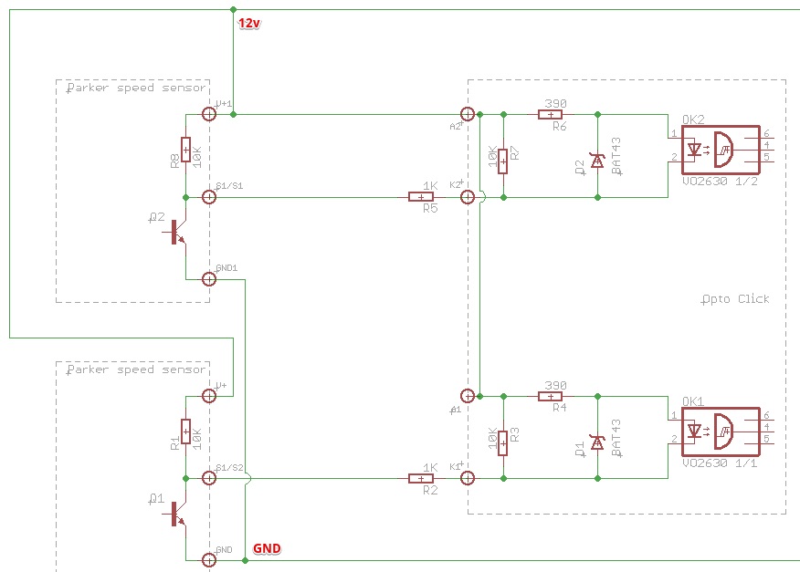
I build simple RPM meter (works fine), but i wish to try use it in harsh environment, so the question is how to properly protect optocouplers input from overvoltage/ESD? In the circuit two optoisolators with a common anode are used, and the cathodes are connected to the collectors of the output transistors of the sensors. In the circuit two optoisolators with a common anode are used, and the cathodes are connected to the collectors of the output transistors of the sensors. I do not have information about the protection applied in the sensors (Parker speed sensors).
Would it then be sufficient to apply "classic" scheme with one TVS between the anode and the cathode of each input (for suppressing overvoltages between the anode and cathode and additional protection against reverse polarity)? Or it would be better to suppress both the anode and cathode lines (relative to ground) with two TVS'es to GND?
Sorry for bad English...


