One good reason for staying away from toroids is that you can't put gaps into them because they are one solid lump. However, with EE ferrites you can easily sand down the centre limb (or put thin spacers in) and make fairly accurate gaps but, why might you want to do this I hear people say.
It's all about maximising the power throughput for a given core size and operating frequency. Sometimes (quite often in fact), it is necessary to make a small gap to reduce the permeability by say 10 to 1. A reduction of ten means you need more windings to obtain the same inductance but you only need the \$\sqrt{10}\$ more windings. This means that you can deliver a bigger H field to the primary and have less core saturation.
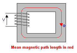
This is because the H field is ampere-turns per metre where the "per metre" part is the mean magnetic length of the core: -
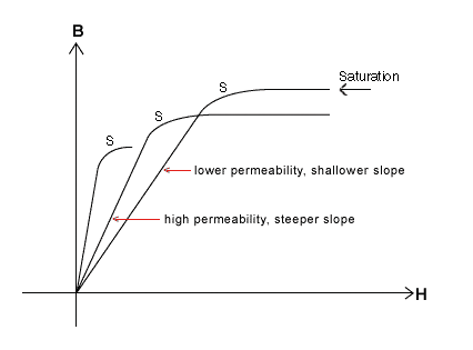
So, for the same inductance (and hence coil current) the turns have increased by \$\sqrt{10}\$ and this makes the H field \$\sqrt{10}\$ times greater but, because permeability has dropped by 10:1, the B field has reduced by \$\sqrt{10}\$ even though the H field has increased by \$\sqrt{10}\$. This is because of the BH curve: -
Simply put, by lowering permeability the ratio B:H lowers. This is why you might want to experiment with gaps. The formula for the expected permeability when gapping is: -
\$\mu_e = \dfrac{1}{\dfrac{1}{\mu_r}+\dfrac{l_g}{l_e}}\$
Where \$l_g\$ and \$l_e\$ are the gap and mean lengths respectively. This formula applies to quite small gaps that don't cause much fringing. \$\mu_e\$ and \$\mu_r\$ are the newgapped and previousungapped permeabilities. So if you have a core that has an ungapped relative permeability 900 and you insert a gap of 1% of the mean length, the gapped permeability would become 90.
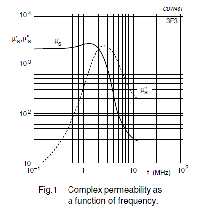
You also have to take into account the core material's ability to handle the operating frequency. Take for instance 3F3 material (one I've recently worked with): -
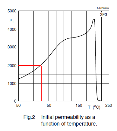
The solid line is the real permeability and the dotted line is effectively the losses. For this material I would want to operate a power application at no greater than 1 MHz - there will be significant warming of the core at this frequency but it should be OK. However, for an inductor, to remain stable, I wouldn't operate it at a frequency greater than about 300 kHz and this is to avoid warming the core too much. Warming the core will change the permeability and alter the inductance value: -
At 25 degC the relative permeability is 2000 and if, through core losses, the temperature rises to 50 degC, then the relative permeability rises to 2500. This means the inductance also rises by 25%. However, if gaps are used and extra turns are used to compensate for those gaps, the temperature effects flatten out considerably.
Consider ungapped 3F3 material of relative permeability 2000 rising to 2500. Now consider what the two relative permeabilities are when gapped at (say) 0.1% of the mean length. If you do the math you get 667 and 714 i.e. an increase of 7.1% (opposed to a change in ungapped permeability of 25%). A 0.5% gap would yield "before" and "after" permeabilities of 181.8 and 185.2 i.e. a change of 1.9% and much more reasonable for an inductor in (say) a filter or an oscillator.
Remember, the temperature rise doesn't have to come from self-heating to affect permeability - changes in ambient temperature also have to be considered but gapping is a very strong tool to keep inductance changes under tight control.


