1
\$\begingroup\$

I'm designing a voltage mode PSU for learning purposes. I've noticed that powdered iron toroids are almost exclusively used in the construction of PFC inductors as well as in low voltage boost converter inductors, with the exception of an electronic HID ballast that I took apart which was a gapped EE65.

I'm currently reading "Transformer and Inductor Design Handbook", where it seems that I can use either EE or toroid cores in the construction of an inductor. I already have a bunch of EE cores. Is there a reason why I shouldn't use one of those as opposed to ordering toroids?

\$\endgroup\$

2 Answers 2

3
\$\begingroup\$

One good reason for staying away from toroids is that you can't put gaps into them because they are one solid lump. However, with EE ferrites you can easily sand down the centre limb (or put thin spacers in) and make fairly accurate gaps but, why might you want to do this I hear people say.

It's all about maximising the power throughput for a given core size and operating frequency. Sometimes (quite often in fact), it is necessary to make a small gap to reduce the permeability by say 10 to 1. A reduction of ten means you need more windings to obtain the same inductance but you only need the \$\sqrt{10}\$ more windings. This means that you can deliver a bigger H field to the primary and have less core saturation.

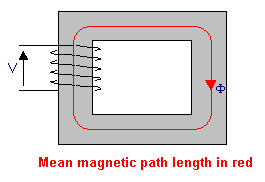
This is because the H field is ampere-turns per metre where the "per metre" part is the mean magnetic length of the core: -
enter image description here

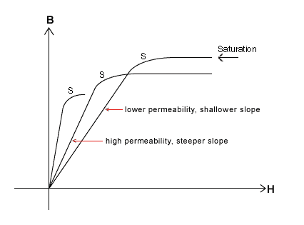
So, for the same inductance (and hence coil current) the turns have increased by \$\sqrt{10}\$ and this makes the H field \$\sqrt{10}\$ times greater but, because permeability has dropped by 10:1, the B field has reduced by \$\sqrt{10}\$ even though the H field has increased by \$\sqrt{10}\$. This is because of the BH curve: -
enter image description here

Simply put, by lowering permeability the ratio B:H lowers. This is why you might want to experiment with gaps. The formula for the expected permeability when gapping is: -

\$\mu_e = \dfrac{1}{\dfrac{1}{\mu_r}+\dfrac{l_g}{l_e}}\$

Where \$l_g\$ and \$l_e\$ are the gap and mean lengths respectively. This formula applies to quite small gaps that don't cause much fringing. \$\mu_e\$ and \$\mu_r\$ are the gapped and ungapped permeabilities. So if you have a core that has an ungapped relative permeability 900 and you insert a gap of 1% of the mean length, the gapped permeability would become 90.

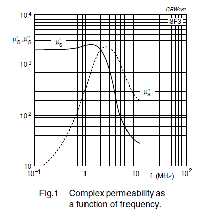
You also have to take into account the core material's ability to handle the operating frequency. Take for instance 3F3 material (one I've recently worked with): -
enter image description here

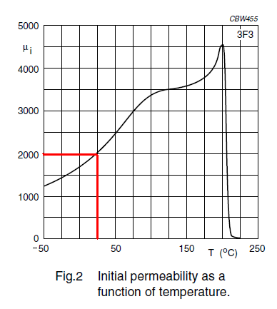
The solid line is the real permeability and the dotted line is effectively the losses. For this material I would want to operate a power application at no greater than 1 MHz - there will be significant warming of the core at this frequency but it should be OK. However, for an inductor, to remain stable, I wouldn't operate it at a frequency greater than about 300 kHz and this is to avoid warming the core too much. Warming the core will change the permeability and alter the inductance value: -
enter image description here

At 25 degC the relative permeability is 2000 and if, through core losses, the temperature rises to 50 degC, then the relative permeability rises to 2500. This means the inductance also rises by 25%. However, if gaps are used and extra turns are used to compensate for those gaps, the temperature effects flatten out considerably.

Consider ungapped 3F3 material of relative permeability 2000 rising to 2500. Now consider what the two relative permeabilities are when gapped at (say) 0.1% of the mean length. If you do the math you get 667 and 714 i.e. an increase of 7.1% (opposed to a change in ungapped permeability of 25%). A 0.5% gap would yield "before" and "after" permeabilities of 181.8 and 185.2 i.e. a change of 1.9% and much more reasonable for an inductor in (say) a filter or an oscillator.

Remember, the temperature rise doesn't have to come from self-heating to affect permeability - changes in ambient temperature also have to be considered but gapping is a very strong tool to keep inductance changes under tight control.

\$\endgroup\$
7
  • \$\begingroup\$ @iuppiter Please wait at least 24 hours before accepting an answer. By giving away the rep bonus already you have removed incentive for others to answer your question. \$\endgroup\$ Commented Jun 2, 2017 at 16:45
  • \$\begingroup\$ Many toroidal cores for PFC, like Kool-Mu, are 'distributed air-gap' by virtue of their composition, and almost impossible to saturate out under bias. \$\endgroup\$ Commented Jun 2, 2017 at 16:47
  • \$\begingroup\$ Your answer seems to agree with the book that I'm currently reading as far as the equations I've learned thus far. I've also noticed that toroids tend to have greater winding limitations. You have also correctly answered many users questions on this forum, so apparently you are very well versed in power electronics. Thank you for the confirmation. \$\endgroup\$
    – iuppiter
    Commented Jun 2, 2017 at 17:47
  • \$\begingroup\$ Thank you for that elaboration. It's far more concise than the book. \$\endgroup\$
    – iuppiter
    Commented Jun 2, 2017 at 22:40
  • \$\begingroup\$ Can you recommend a book on magnetic theory that all equations are given in SI units? \$\endgroup\$
    – iuppiter
    Commented Jun 20, 2017 at 2:04
3
\$\begingroup\$

I've worked on both EE and toroidal core designs for PFC inductors. Both have advantages and disadvantages.

With an EE-type core, you can control the gap for precise inductance. You will get a flat inductance-vs-bias curve until you hit the saturation point, at which time the inductance will drop off dramatically. The choice of core material in EE is (in my experience) larger than you can get in toroidal form, so you can often get lower-loss material choices.

Many of the toroidal cores for PFC have 'distributed gap' construction - an example is Kool-Mu by Magnetics Inc., but there are many others. This material tends to have lower permeability but has a very gradual inductance roll-off under bias - some claim that it "impossible" to saturate out a Kool-Mu PFC choke - not entirely true but they can run under very heavy bias currents and survive. This is called a 'swinging choke' in power supply parlance. Having higher inductance at lighter loads can be beneficial if you are trying to stay in DCM.

For prototyping I like toroids. You can just wind turns on them and install them. An EE-core inductor needs a bobbin, may need gapping material, glue or epoxy to hold the gap, etc. etc. and so on. That being said, there's no electrical reason not to use what you have on hand - it will work just fine if your design is correct and the core material is appropriate.

\$\endgroup\$
5
  • \$\begingroup\$ To deliver the same power with a toroid, rather than using the EE42 wouldn't I need a toroid almost the size of a doughnut? If I'm correct you shouldn't occupy more than 20% of the inner diameter of the toroid, which limits the amount of windings and also seems to make the EE core a superior choice, as long as I maintain the B within the Bsat boundaries. Correct me if i'm wrong. This is all still theoretical to me. I haven't wound an inductor to boost 170V to 360V, operating at 100kHz yet. I've only made low voltage boost converters. \$\endgroup\$
    – iuppiter
    Commented Jun 2, 2017 at 17:16
  • \$\begingroup\$ The EE cores I buy come with bobbins so that's not an issue. Winding a toroid requires that you pre-cut the wire to length (that's a pain) and pull the wire through the loop for as many windings as is necessary (more pain). Where you can wind the bobbin right from the spool. Ferrites are also designed to operate at higher frequencies without the nasty eddy currents, allowing for a smaller inductor. So from what I can see, in my limited experience, the E core wins! \$\endgroup\$
    – iuppiter
    Commented Jun 2, 2017 at 18:14
  • \$\begingroup\$ If you have the bobbins already you're ahead of the game. Gapping can be tricky unless you are using external shims - it can be tricky to precisely grind / sand cores otherwise. I've worked on designs at 3kW with both toroidal and EE core PFC inductors (boosting from 120 - 370VDC to 400VDC, both single phase and multiphase). \$\endgroup\$ Commented Jun 3, 2017 at 12:44
  • \$\begingroup\$ The gapping seems fairly simple to calculate, but I know that 1mm drastically increases the core reluctance. I noticed that in a very informative youtube video on inductance, where he put two halves of a core together with and without pressure applied and there was a 10μΗ difference. I imagine without pressure applied there was maybe .01mm(probably less) difference. I'm actually working on a dual phase PFC stage to keep the ripple to a minimum. \$\endgroup\$
    – iuppiter
    Commented Jun 5, 2017 at 15:30
  • \$\begingroup\$ Mechanical force plays a role for sure. We often use epoxy with embedded glass beads to control the gap more precisely. \$\endgroup\$ Commented Jun 5, 2017 at 15:41

Your Answer

By clicking “Post Your Answer”, you agree to our terms of service and acknowledge you have read our privacy policy.

Not the answer you're looking for? Browse other questions tagged or ask your own question.