added 1231 characters in body
Source Link
jonk
  • 78.7k
  • 6
  • 81
  • 195

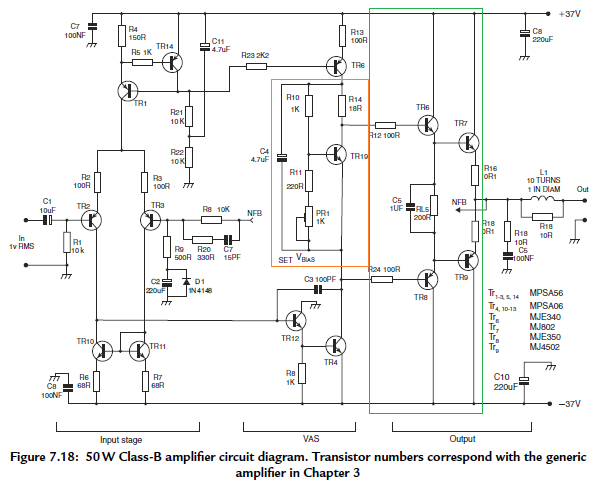
It also uses a \$V_{BE}\$ multiplier instead of a pair of diodes (in the orange box I added.) But again, the idea is the same. Just in this case you can tweak the voltage. Also, this \$V_{BE}\$ multiplier includes a resistor in the collector, \$R_{14}\$, that compensates the \$V_{BE}\$ multiplier for the Early Effect in \$TR_{19}\$. Again, this is just an adjustment to the basic idea but needed to slightly improve its performance in the circuit.

Note that this amplifier system uses two supply rails, plus ground. Namely, \$\pm 37\:\textrm{V}\$. From the equation I mentioned above, you can work out that this means \$P=\frac{V_P^2}{2\cdot R}=\frac{\left(37\:\textrm{V}\right)^2}{2\cdot 8\:\Omega}\approx 85\:\textrm{W}\$. However, if you count diode drops from the output back to either rail and roughly consider the necessary collector-emitter voltages required by a few BJTs there, you can easily see a need for about \$6\:\textrm{V}\$ of overhead on each side of ground. So this brings it back to about \$60\:\textrm{W}\$. Other considerations bring it down further, to the stated \$50\:\textrm{W}\$ rating mentioned by the author.

The use of two rails means that an output capacitor can be avoided, directly driving one end of a grounded speaker. An added reason why dual supply rails (or else a bridge-tied load) might be worth considering.

The circuit also includes negative feedback (look for the NFB terminal mark on the schematic in two places.) This helps by using some of the open loop gain to help linearize the output and to deal with issues such as cross-over distortion that may be present.

Real circuits are like that. You start with a basic idea that does work somewhat and then you add more to it in order to deal with various unwanted behaviors, correcting those that are more important and ignoring those that you can accept or tolerate.

It also uses a \$V_{BE}\$ multiplier instead of a pair of diodes. But again, the idea is the same. Just in this case you can tweak the voltage. Also, this \$V_{BE}\$ multiplier includes a resistor in the collector, \$R_{14}\$, that compensates the \$V_{BE}\$ multiplier for the Early Effect in \$TR_{19}\$. Again, this is just an adjustment to the basic idea but needed to slightly improve its performance in the circuit.

Real circuits are like that. You start with a basic idea that does work and then you add more to it in order to deal with various unwanted behaviors, correcting those that are more important and ignoring those that you can accept or tolerate.

It also uses a \$V_{BE}\$ multiplier instead of a pair of diodes (in the orange box I added.) But again, the idea is the same. Just in this case you can tweak the voltage. Also, this \$V_{BE}\$ multiplier includes a resistor in the collector, \$R_{14}\$, that compensates the \$V_{BE}\$ multiplier for the Early Effect in \$TR_{19}\$. Again, this is just an adjustment to the basic idea but needed to slightly improve its performance in the circuit.

Note that this amplifier system uses two supply rails, plus ground. Namely, \$\pm 37\:\textrm{V}\$. From the equation I mentioned above, you can work out that this means \$P=\frac{V_P^2}{2\cdot R}=\frac{\left(37\:\textrm{V}\right)^2}{2\cdot 8\:\Omega}\approx 85\:\textrm{W}\$. However, if you count diode drops from the output back to either rail and roughly consider the necessary collector-emitter voltages required by a few BJTs there, you can easily see a need for about \$6\:\textrm{V}\$ of overhead on each side of ground. So this brings it back to about \$60\:\textrm{W}\$. Other considerations bring it down further, to the stated \$50\:\textrm{W}\$ rating mentioned by the author.

The use of two rails means that an output capacitor can be avoided, directly driving one end of a grounded speaker. An added reason why dual supply rails (or else a bridge-tied load) might be worth considering.

The circuit also includes negative feedback (look for the NFB terminal mark on the schematic in two places.) This helps by using some of the open loop gain to help linearize the output and to deal with issues such as cross-over distortion that may be present.

Real circuits are like that. You start with a basic idea that does work somewhat and then you add more to it in order to deal with various unwanted behaviors, correcting those that are more important and ignoring those that you can accept or tolerate.

added 1231 characters in body
Source Link
jonk
  • 78.7k
  • 6
  • 81
  • 195

Here's an example of an amplifier circuit taken from Douglas Self's 5th edition book mentioned at the bottom, below.

It'senter image description here

The basic ideas are still a terrible way to gopresent there.

For example, I highlighted in green the equivalent it uses for what I showed as \$Q_1\$ and \$Q_2\$ in the circuits presented earlier, above. It uses four BJTs, not two. But the basic idea is the same. It adds some emitter degeneration resistors (small values.) But again, the basic idea remains the same.

It also uses a \$V_{BE}\$ multiplier instead of a pair of diodes. But again, the idea is the same. Just in this case you can tweak the voltage. Also, this \$V_{BE}\$ multiplier includes a resistor in the collector, \$R_{14}\$, that compensates the \$V_{BE}\$ multiplier for the Early Effect in \$TR_{19}\$. Again, this is just an adjustment to the basic idea but needed to slightly improve its performance in the circuit.

Real circuits are like that. You start with a basic idea that does work and then you add more to it in order to deal with various unwanted behaviors, correcting those that are more important and ignoring those that you can accept or tolerate.


It's still a terrible way to go.


Here's an example of an amplifier circuit taken from Douglas Self's 5th edition book mentioned at the bottom, below.

enter image description here

The basic ideas are still present there.

For example, I highlighted in green the equivalent it uses for what I showed as \$Q_1\$ and \$Q_2\$ in the circuits presented earlier, above. It uses four BJTs, not two. But the basic idea is the same. It adds some emitter degeneration resistors (small values.) But again, the basic idea remains the same.

It also uses a \$V_{BE}\$ multiplier instead of a pair of diodes. But again, the idea is the same. Just in this case you can tweak the voltage. Also, this \$V_{BE}\$ multiplier includes a resistor in the collector, \$R_{14}\$, that compensates the \$V_{BE}\$ multiplier for the Early Effect in \$TR_{19}\$. Again, this is just an adjustment to the basic idea but needed to slightly improve its performance in the circuit.

Real circuits are like that. You start with a basic idea that does work and then you add more to it in order to deal with various unwanted behaviors, correcting those that are more important and ignoring those that you can accept or tolerate.


added 58 characters in body
Source Link
jonk
  • 78.7k
  • 6
  • 81
  • 195

In your case, you are just at the cusp of where your circuit can't possibly work well... unless you change the problem by removing your speaker load. So you are ready to advance, I think. Try one of the following books. I have all of these and have read them (as well as I've been able):

  • Douglas Self, "Audio Power Amplifier Design Handbook," 5th edition or better
  • Bob Cordell, "Designing Audio Power Amplifiers"
  • Douglas Self, "Small Signal Audio Design"
  • Jim Williams, "Analog Circuit Design"
  • Paul Horowitz and Winfield Hill, "The Art of Electronics," 3rd edition
  • Thomas C Hayes (plus Paul Horowitz), "Learning the Art of Electronics"

In your case, you are just at the cusp of where your circuit can't possibly work well... unless you change the problem by removing your speaker load. So you are ready to advance, I think. Try one of the following books:

  • Douglas Self, "Audio Power Amplifier Design Handbook," 5th edition or better
  • Bob Cordell, "Designing Audio Power Amplifiers"
  • Douglas Self, "Small Signal Audio Design"
  • Jim Williams, "Analog Circuit Design"
  • Paul Horowitz and Winfield Hill, "The Art of Electronics," 3rd edition
  • Thomas C Hayes (plus Paul Horowitz), "Learning the Art of Electronics"

In your case, you are just at the cusp of where your circuit can't possibly work well... unless you change the problem by removing your speaker load. So you are ready to advance, I think. Try one of the following books. I have all of these and have read them (as well as I've been able):

  • Douglas Self, "Audio Power Amplifier Design Handbook," 5th edition
  • Bob Cordell, "Designing Audio Power Amplifiers"
  • Douglas Self, "Small Signal Audio Design"
  • Jim Williams, "Analog Circuit Design"
  • Paul Horowitz and Winfield Hill, "The Art of Electronics," 3rd edition
  • Thomas C Hayes (plus Paul Horowitz), "Learning the Art of Electronics"
added 2849 characters in body
Source Link
jonk
  • 78.7k
  • 6
  • 81
  • 195
Loading
deleted 3 characters in body
Source Link
jonk
  • 78.7k
  • 6
  • 81
  • 195
Loading
Source Link
jonk
  • 78.7k
  • 6
  • 81
  • 195
Loading