added 74 characters in body
Source Link
user136077
user136077

Electric circuits have totally different structure than block diagrams. In electric circuits there are voltages between the nodes and those voltages cause currents along the wires and components between the nodes. In addition there are multiport parts like amplifiers or transformers.

In block diagrams there are no such things. They are graphical presentations how quantities depend on each other. Block diagram is one way to write a group of equations.

There's no look-alike equivalence between circuit diagrams and block diagrams because the blocks present terms in equations, not components. Thus it's totally useless to try to find the little step that transforms the opamp circuit to your generic feedback block diagram, altough the resistors a little resemble rectangular blocks.

We have several ways to write the circuit equations for a circuit. They all lead to the same solution of currents and voltages, but as block diagrams they are totally different. Some of them can resemble your generic feedback model.

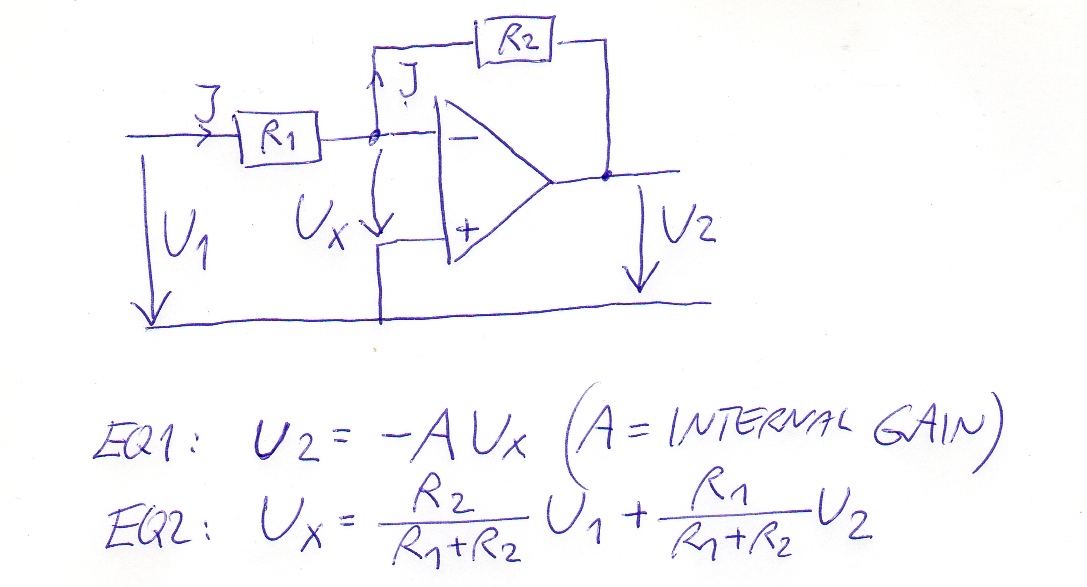
Lets try one of the possiblities. We assume the opamp to be ideal, so the current I from R1 continues to R2, no current to opamp input.

The output voltage U2 is negated and amplified opamp input voltage Ux. We write it U2=U2 = -A*Ux

The opamp input voltage Ux is a superposition of U1 and U2. From both sources the Ux is given through a voltage divider:. This assumes the opamp input current to be zero, there's the same current I through R1 and R2.

enter image description here

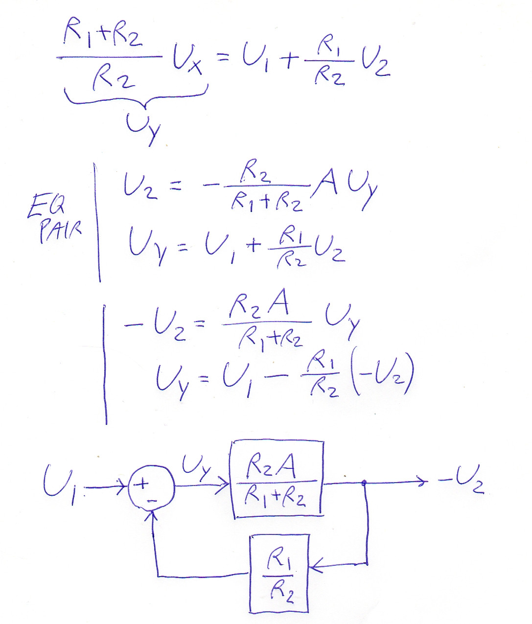
This is far away from the generic feedback model equations. We must write equivalent equations with non-physical quantities which we form by multiplying the equations retaining the equality:

enter image description here

U1 is made separate term by multiplying EQ2 by (R1+R2)/R2. In the place of Ux we have non-physical quantity Uy. It's compensated in EQ1 by dividing. In the place of U2 we have its negation -U2.

Now the system is formally like the generic feedback diagram. From it we for example see directly: When we let the gain A to grow to infinity, the circuit amplifies the usual way: U2 = -(R2/R1)*U1. That's the inverse of the feedback factor.

Electric circuits have totally different structure than block diagrams. In electric circuits there are voltages between the nodes and those voltages cause currents along the wires and components between the nodes. In addition there are multiport parts like amplifiers or transformers.

In block diagrams there are no such things. They are graphical presentations how quantities depend on each other. Block diagram is one way to write a group of equations.

There's no look-alike equivalence between circuit diagrams and block diagrams because the blocks present terms in equations, not components. Thus it's totally useless to try to find the little step that transforms the opamp circuit to your generic feedback block diagram, altough the resistors a little resemble rectangular blocks.

We have several ways to write the circuit equations for a circuit. They all lead to the same solution of currents and voltages, but as block diagrams they are totally different. Some of them can resemble your generic feedback model.

Lets try one of the possiblities. We assume the opamp to be ideal, so the current I from R1 continues to R2, no current to opamp input.

The output voltage U2 is negated and amplified opamp input voltage Ux. We write it U2=-A*Ux

The opamp input voltage Ux is a superposition of U1 and U2. From both sources the Ux is given through a voltage divider:

enter image description here

This is far away from the generic feedback model equations. We must write equivalent equations with non-physical quantities which we form by multiplying the equations retaining the equality:

enter image description here

U1 is made separate term by multiplying EQ2 by (R1+R2)/R2. In the place of Ux we have non-physical quantity Uy. It's compensated in EQ1 by dividing. In the place of U2 we have its negation -U2.

Now the system is formally like the generic feedback diagram. From it we for example see directly: When we let the gain A to grow to infinity, the circuit amplifies the usual way: U2 = -(R2/R1)*U1. That's the inverse of the feedback factor.
Electric circuits have totally different structure than block diagrams. In electric circuits there are voltages between the nodes and those voltages cause currents along the wires and components between the nodes. In addition there are multiport parts like amplifiers or transformers.

In block diagrams there are no such things. They are graphical presentations how quantities depend on each other. Block diagram is one way to write a group of equations.

There's no look-alike equivalence between circuit diagrams and block diagrams because the blocks present terms in equations, not components. Thus it's totally useless to try to find the little step that transforms the opamp circuit to your generic feedback block diagram, altough the resistors a little resemble rectangular blocks.

We have several ways to write the circuit equations for a circuit. They all lead to the same solution of currents and voltages, but as block diagrams they are totally different. Some of them can resemble your generic feedback model.

Lets try one of the possiblities. The output voltage U2 is negated and amplified opamp input voltage Ux. We write it U2 = -A*Ux

The opamp input voltage Ux is a superposition of U1 and U2. From both sources the Ux is given through a voltage divider. This assumes the opamp input current to be zero, there's the same current I through R1 and R2.

enter image description here

This is far away from the generic feedback model equations. We must write equivalent equations with non-physical quantities which we form by multiplying the equations retaining the equality:

enter image description here

U1 is made separate term by multiplying EQ2 by (R1+R2)/R2. In the place of Ux we have non-physical quantity Uy. It's compensated in EQ1 by dividing. In the place of U2 we have its negation -U2.

Now the system is formally like the generic feedback diagram. From it we for example see directly: When we let the gain A to grow to infinity, the circuit amplifies the usual way: U2 = -(R2/R1)*U1. That's the inverse of the feedback factor.

added 74 characters in body
Source Link
user136077
user136077

Electric circuits have totally different structure than block diagrams. In electric circuits there are voltages between the nodes and those voltages cause currents along the wires and components between the nodes. In addition there are multiport parts like amplifiers or transformers.

In block diagrams there are no such things. They are graphical presentations how quantities depend on each other. Block diagram is one way to write a group of equations.

There's no look-alike equivalence between circuit diagrams and block diagrams because the blocks present terms in equations, not components. Thus it's totally useless to try to find the little step that transforms the opamp circuit to your generic feedback block diagram, altough the resistors a little resemble rectangular blocks.

We have several ways to write the circuit equations for a circuit. They all lead to the same solution of currents and voltages, but as block diagrams they are totally different. Some of them can resemble your generic feedback model.

Lets try one of the possiblities. We assume the opamp to be ideal, so the current I from R1 continues to R2, no current to opamp input.

The output voltage U2 is negated and amplified opamp input voltage Ux. We write it I2 =U2=-A*Ux

The opamp input voltage Ux is a superposition of U1 and U2. From both sources the Ux is given through a voltage divider:

enter image description here

This is far away from the generic feedback model equations. We must write equivalent equations with non-physical quantities which we form by multiplying the equations retaining the equality:

enter image description here

U1 is made separate term by multiplying EQ2 by (R1+R2)/R2. In the place of Ux we have non-physical quantity Uy. It's compensated in EQ1 by dividing. In the place of U2 we have its negation -U2.

Now the system is formally like the generic feedback diagram. From it we for example see directly: When we let the gain A to grow to infinity, the circuit amplifies the usual way: U2 = -(R2/R1)*U1. That's the inverse of the feedback factor.

Electric circuits have totally different structure than block diagrams. In electric circuits there are voltages between the nodes and those voltages cause currents along the wires and components between the nodes. In addition there are multiport parts like amplifiers or transformers.

In block diagrams there are no such things. They are graphical presentations how quantities depend on each other. Block diagram is one way to write a group of equations.

There's no look-alike equivalence between circuit diagrams and block diagrams because the blocks present terms in equations, not components. Thus it's totally useless to try to find the little step that transforms the opamp circuit to your generic feedback block diagram, altough the resistors a little resemble rectangular blocks.

We have several ways to write the circuit equations for a circuit. They all lead to the same solution of currents and voltages, but as block diagrams they are totally different. Some of them can resemble your generic feedback model.

Lets try one of the possiblities. We assume the opamp to be ideal, so the current I from R1 continues to R2, no current to opamp input.

The output voltage U2 is negated and amplified opamp input voltage Ux. We write it I2 =-A*Ux

The opamp input voltage Ux is a superposition of U1 and U2. From both sources the Ux is given through a voltage divider:

enter image description here

This is far away from the generic feedback model equations. We must write equivalent equations with non-physical quantities which we form by multiplying the equations retaining the equality:

enter image description here

U1 is made separate term by multiplying EQ2 by (R1+R2)/R2. In the place of Ux we have non-physical quantity Uy. It's compensated in EQ1 by dividing. In the place of U2 we have its negation -U2.

Now the system is formally like the generic feedback diagram. From it we for example see directly: When we let the gain A to grow to infinity, the circuit amplifies the usual way: U2 = -(R2/R1)*U1. That's the inverse of the feedback factor.

Electric circuits have totally different structure than block diagrams. In electric circuits there are voltages between the nodes and those voltages cause currents along the wires and components between the nodes. In addition there are multiport parts like amplifiers or transformers.

In block diagrams there are no such things. They are graphical presentations how quantities depend on each other. Block diagram is one way to write a group of equations.

There's no look-alike equivalence between circuit diagrams and block diagrams because the blocks present terms in equations, not components. Thus it's totally useless to try to find the little step that transforms the opamp circuit to your generic feedback block diagram, altough the resistors a little resemble rectangular blocks.

We have several ways to write the circuit equations for a circuit. They all lead to the same solution of currents and voltages, but as block diagrams they are totally different. Some of them can resemble your generic feedback model.

Lets try one of the possiblities. We assume the opamp to be ideal, so the current I from R1 continues to R2, no current to opamp input.

The output voltage U2 is negated and amplified opamp input voltage Ux. We write it U2=-A*Ux

The opamp input voltage Ux is a superposition of U1 and U2. From both sources the Ux is given through a voltage divider:

enter image description here

This is far away from the generic feedback model equations. We must write equivalent equations with non-physical quantities which we form by multiplying the equations retaining the equality:

enter image description here

U1 is made separate term by multiplying EQ2 by (R1+R2)/R2. In the place of Ux we have non-physical quantity Uy. It's compensated in EQ1 by dividing. In the place of U2 we have its negation -U2.

Now the system is formally like the generic feedback diagram. From it we for example see directly: When we let the gain A to grow to infinity, the circuit amplifies the usual way: U2 = -(R2/R1)*U1. That's the inverse of the feedback factor.

added 74 characters in body
Source Link
user136077
user136077

Electric circuits have totally different structure than block diagrams. In electric circuits there are voltages between the nodes and those voltages cause currents along the wires and components between the nodes. In addition there are multiport parts like amplifiers or transformers.

In block diagrams there are no such things. They are graphical presentations how quantities depend on each other. Block diagram is one way to write a group of equations. There's

There's no look-alike equivalence between circuit diagrams and block diagrams because the blocks present terms in equations, not components. It's Thus it's totally useless to try to find athe little step that transforms the opamp circuit to your generic feedback block diagram, altough the resistors a little resemble rectangular blocks.

We have several ways to write the circuit equations for a circuit. They all lead to the same solution of currents and voltages, but as block diagrams they are totally different. Some of them can resemble your generic feedback model.

Lets try one of the possiblities. We assume the opamp to be ideal, so the current I from R1 continues to R2, no current to opamp input.

The output voltage U2 is invertednegated and amlifiedamplified opamp input voltage Ux. We write it I2 =-A*Ux

The opamp input voltage Ux is a superposition of U1 and U2. From both sources the Ux is given through a voltage divider:

enter image description here

This is far away from the generic feedback model equations. We must write equivalent equations with non-physical quantities which we form by multiplying the equations retaining the equality:

enter image description here

U1 is made separate term by multiplying EQ2 by (R1+R2)/R2. In the place of Ux we have non-physical quantity Uy. It's compensated in EQ1 by dividing. In the place of U2 we have its inversenegation -U2.

Now the system is formally like the generic feedback diagram. From it we for example see directly: When we let the gain A to grow to infinity, the circuit amplifies the usual way: U2 = -(R2/R1)*U1. That's the inverse of the feedback factor.

Electric circuits have totally different structure than block diagrams. In electric circuits there are voltages between the nodes and those voltages cause currents along the wires and components between the nodes. In addition there are multiport parts like amplifiers or transformers.

In block diagrams there are no such things. They are graphical presentations how quantities depend on each other. Block diagram is one way to write a group of equations. There's no look-alike equivalence between circuit diagrams and block diagrams. It's totally useless to try to find a little step that transforms the opamp circuit to your generic feedback block diagram, altough the resistors a little resemble rectangular blocks.

We have several ways to write the circuit equations for a circuit. They all lead to the same solution of currents and voltages, but as block diagrams they are totally different. Some of them can resemble your generic feedback model.

Lets try one of the possiblities. We assume the opamp to be ideal, so the current I from R1 continues to R2, no current to opamp input.

The output voltage U2 is inverted and amlified input voltage Ux. The input voltage Ux is a superposition of U1 and U2. From both sources the Ux is given through a voltage divider:

enter image description here

This is far away from the generic feedback model equations. We must write equivalent equations with non-physical quantities which we form by multiplying the equations retaining the equality:

enter image description here

U1 is made separate term by multiplying EQ2 by (R1+R2)/R2. In the place of Ux we have non-physical quantity Uy. It's compensated in EQ1 by dividing. In the place of U2 we have its inverse -U2.

Now the system is formally like the generic feedback diagram. From it we for example see directly: When we let the gain A to grow to infinity, the circuit amplifies the usual way: U2 = -(R2/R1)*U1. That's the inverse of the feedback factor.

Electric circuits have totally different structure than block diagrams. In electric circuits there are voltages between the nodes and those voltages cause currents along the wires and components between the nodes. In addition there are multiport parts like amplifiers or transformers.

In block diagrams there are no such things. They are graphical presentations how quantities depend on each other. Block diagram is one way to write a group of equations.

There's no look-alike equivalence between circuit diagrams and block diagrams because the blocks present terms in equations, not components. Thus it's totally useless to try to find the little step that transforms the opamp circuit to your generic feedback block diagram, altough the resistors a little resemble rectangular blocks.

We have several ways to write the circuit equations for a circuit. They all lead to the same solution of currents and voltages, but as block diagrams they are totally different. Some of them can resemble your generic feedback model.

Lets try one of the possiblities. We assume the opamp to be ideal, so the current I from R1 continues to R2, no current to opamp input.

The output voltage U2 is negated and amplified opamp input voltage Ux. We write it I2 =-A*Ux

The opamp input voltage Ux is a superposition of U1 and U2. From both sources the Ux is given through a voltage divider:

enter image description here

This is far away from the generic feedback model equations. We must write equivalent equations with non-physical quantities which we form by multiplying the equations retaining the equality:

enter image description here

U1 is made separate term by multiplying EQ2 by (R1+R2)/R2. In the place of Ux we have non-physical quantity Uy. It's compensated in EQ1 by dividing. In the place of U2 we have its negation -U2.

Now the system is formally like the generic feedback diagram. From it we for example see directly: When we let the gain A to grow to infinity, the circuit amplifies the usual way: U2 = -(R2/R1)*U1. That's the inverse of the feedback factor.

edited body
Source Link
user136077
user136077
Loading
edited body
Source Link
user136077
user136077
Loading
edited body
Source Link
user136077
user136077
Loading
added 37 characters in body
Source Link
user136077
user136077
Loading
added 433 characters in body
Source Link
user136077
user136077
Loading
added 328 characters in body
Source Link
user136077
user136077
Loading
added 328 characters in body
Source Link
user136077
user136077
Loading
Source Link
user136077
user136077
Loading