Notice removed Improve details by Harry Svensson
Bounty Ended with glen_geek's answer chosen by Harry Svensson
Improved readability, replaced < ` > with < ' >.
Source Link

I`mI'm trying to build a frequency modulated LC oscillator but all circuits I`veI've tried have terrible mains hum after demodultaion.

The oscillator is tuned by capacitive sensor but I`mI'm using a fixed capacitor instead until I solve this problem. I`veI've tried different topologies: Franklin, Clapp, Vackář, Hartley at different frequencies from 60 to 500 MHz but there`sthere's no difference between them in terms of mains hum. I`mI'm using an SDR receiver for demodulation, it works fine and cannot be the source of hum. Using battery instead of AC supply didn`tdidn't help. I`m using 10 µF and 10 nF capacitors for decoupling. Using physically smaller inductors helped a little, but the noise is still unacceptable.

As suggested in comments, I`veI've tested all circuit nodes with and without powering the circuit and 50 Hz component appears only at the antenna output.

Uploading my setup and schematics as requested. The setup is just an SDR receiver and the oscillator with a piece of wire at the output as a makeshift antenna. The capacitive sensor Cvar is absent, as I`mI'm using a fixed capacitor C4 instead.

I`veI've made a new board with a ground plane and a nickel silver EMI shield. I`veI've added a 1.8V LD1117 regulator and 100pF and 390pF NP0 decoupling capacitors — and still no luck. There are no significant changes in the noise performance. Unfortunately, I couldn`tcouldn't find an iron box to put the whole circuit in, but I`mI'm almost sure there are some clever circuit and PCB design techniques that do not require magnetic shielding. For example, I`veI've tested the SDR receiver on a cheap unshielded FM transmitter: there`sthere's no hum at all, even with the volume maxed out, so the culprit is definitely the circuit and PCB design.

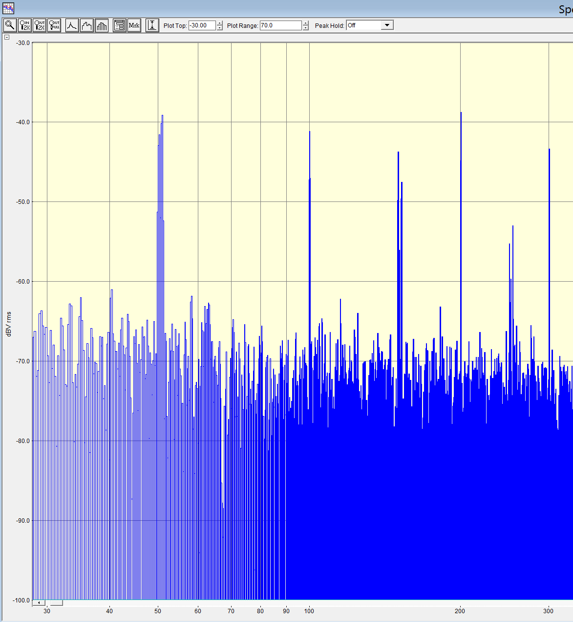
Also, as suggested in the answer below, I`veI've recorded an IF from my SDR receiver and generated its spectrum at low frequencies.

Fig. 6a: C4 = 1.5 pF enter image description hereenter image description here

Fig. 6b: C4 = 2.7 pF enter image description hereenter image description here

Unfortunately, I`veI've got no other capacitors in the range between 1 and 10 pF to make further tests (the oscillator won`twon't start with C4 ≥ 10 pF). I guess that the AC line noise picked by PCB traces and L2 changes the gate capacitance of J1, and increasing the value of C4 reduces the influence of those changes on frequency. This is also confirmed by adding a strong noise source, e.g. a cell phone making a call. You can see large spikes on Fig. 6c and the frequency does actually increase when I add a noise source, meaning that the gate capacitance of J1 is inversely proportional to voltage. Makes sense to me. Seems like I need to either reduce coupling between J1 and LC tank or add some high-pass filtering between them, but I`mI'm not sure what the best way of doing it is.

I`m trying to build a frequency modulated LC oscillator but all circuits I`ve tried have terrible mains hum after demodultaion.

The oscillator is tuned by capacitive sensor but I`m using a fixed capacitor instead until I solve this problem. I`ve tried different topologies: Franklin, Clapp, Vackář, Hartley at different frequencies from 60 to 500 MHz but there`s no difference between them in terms of mains hum. I`m using an SDR receiver for demodulation, it works fine and cannot be the source of hum. Using battery instead of AC supply didn`t help. I`m using 10 µF and 10 nF capacitors for decoupling. Using physically smaller inductors helped a little, but the noise is still unacceptable.

As suggested in comments, I`ve tested all circuit nodes with and without powering the circuit and 50 Hz component appears only at the antenna output.

Uploading my setup and schematics as requested. The setup is just an SDR receiver and the oscillator with a piece of wire at the output as a makeshift antenna. The capacitive sensor Cvar is absent, as I`m using a fixed capacitor C4 instead.

I`ve made a new board with a ground plane and a nickel silver EMI shield. I`ve added a 1.8V LD1117 regulator and 100pF and 390pF NP0 decoupling capacitors — and still no luck. There are no significant changes in the noise performance. Unfortunately, I couldn`t find an iron box to put the whole circuit in, but I`m almost sure there are some clever circuit and PCB design techniques that do not require magnetic shielding. For example, I`ve tested the SDR receiver on a cheap unshielded FM transmitter: there`s no hum at all, even with the volume maxed out, so the culprit is definitely the circuit and PCB design.

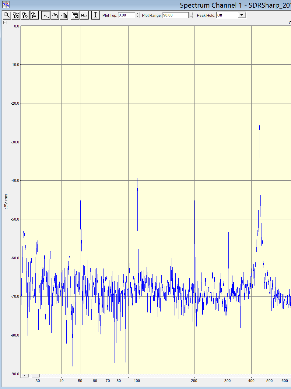
Also, as suggested in the answer below, I`ve recorded an IF from my SDR receiver and generated its spectrum at low frequencies.

Fig. 6a: C4 = 1.5 pF enter image description here

Fig. 6b: C4 = 2.7 pF enter image description here

Unfortunately, I`ve got no other capacitors in the range between 1 and 10 pF to make further tests (the oscillator won`t start with C4 ≥ 10 pF). I guess that the AC line noise picked by PCB traces and L2 changes the gate capacitance of J1, and increasing the value of C4 reduces the influence of those changes on frequency. This is also confirmed by adding a strong noise source, e.g. a cell phone making a call. You can see large spikes on Fig. 6c and the frequency does actually increase when I add a noise source, meaning that the gate capacitance of J1 is inversely proportional to voltage. Makes sense to me. Seems like I need to either reduce coupling between J1 and LC tank or add some high-pass filtering between them, but I`m not sure what the best way of doing it is.
I'm trying to build a frequency modulated LC oscillator but all circuits I've tried have terrible mains hum after demodultaion.

The oscillator is tuned by capacitive sensor but I'm using a fixed capacitor instead until I solve this problem. I've tried different topologies: Franklin, Clapp, Vackář, Hartley at different frequencies from 60 to 500 MHz but there's no difference between them in terms of mains hum. I'm using an SDR receiver for demodulation, it works fine and cannot be the source of hum. Using battery instead of AC supply didn't help. I`m using 10 µF and 10 nF capacitors for decoupling. Using physically smaller inductors helped a little, but the noise is still unacceptable.

As suggested in comments, I've tested all circuit nodes with and without powering the circuit and 50 Hz component appears only at the antenna output.

Uploading my setup and schematics as requested. The setup is just an SDR receiver and the oscillator with a piece of wire at the output as a makeshift antenna. The capacitive sensor Cvar is absent, as I'm using a fixed capacitor C4 instead.

I've made a new board with a ground plane and a nickel silver EMI shield. I've added a 1.8V LD1117 regulator and 100pF and 390pF NP0 decoupling capacitors — and still no luck. There are no significant changes in the noise performance. Unfortunately, I couldn't find an iron box to put the whole circuit in, but I'm almost sure there are some clever circuit and PCB design techniques that do not require magnetic shielding. For example, I've tested the SDR receiver on a cheap unshielded FM transmitter: there's no hum at all, even with the volume maxed out, so the culprit is definitely the circuit and PCB design.

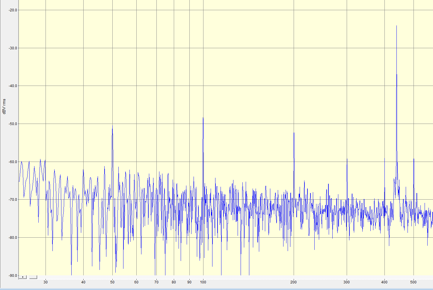
Also, as suggested in the answer below, I've recorded an IF from my SDR receiver and generated its spectrum at low frequencies.

Fig. 6a: C4 = 1.5 pF enter image description here

Fig. 6b: C4 = 2.7 pF enter image description here

Unfortunately, I've got no other capacitors in the range between 1 and 10 pF to make further tests (the oscillator won't start with C4 ≥ 10 pF). I guess that the AC line noise picked by PCB traces and L2 changes the gate capacitance of J1, and increasing the value of C4 reduces the influence of those changes on frequency. This is also confirmed by adding a strong noise source, e.g. a cell phone making a call. You can see large spikes on Fig. 6c and the frequency does actually increase when I add a noise source, meaning that the gate capacitance of J1 is inversely proportional to voltage. Makes sense to me. Seems like I need to either reduce coupling between J1 and LC tank or add some high-pass filtering between them, but I'm not sure what the best way of doing it is.
edited body
Source Link
hidefromkgb
  • 317
  • 1
  • 14

Fig. 6a: C4 = 1.5 pF enter image description hereenter image description here

Fig. 6b: C4 = 2.7 pF enter image description hereenter image description here

Fig. 6a: C4 = 1.5 pF enter image description here

Fig. 6b: C4 = 2.7 pF enter image description here

Fig. 6a: C4 = 1.5 pF enter image description here

Fig. 6b: C4 = 2.7 pF enter image description here

added 84 characters in body
Source Link
hidefromkgb
  • 317
  • 1
  • 14

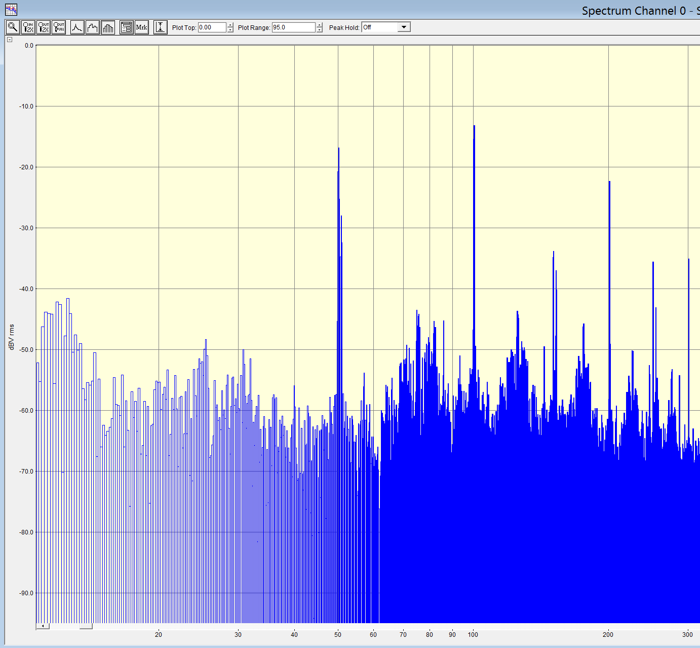
Increasing C4 (see Fig. 3c) reduces the noise significantly. Look at the demodulated signal spectrums (the 440 Hz component is a test signal recorded from the sensor for SNR measurement):

Fig. 6a: C4 = 1.5 pF enter image description hereenter image description here

Fig. 6b: C4 = 2.7 pF enter image description hereenter image description here

Increasing C4 (see Fig. 3c) reduces the noise significantly. Look at the demodulated signal spectrums:

Fig. 6a: C4 = 1.5 pF enter image description here

Fig. 6b: C4 = 2.7 pF enter image description here

Increasing C4 (see Fig. 3c) reduces the noise significantly. Look at the demodulated signal spectrums (the 440 Hz component is a test signal recorded from the sensor for SNR measurement):

Fig. 6a: C4 = 1.5 pF enter image description here

Fig. 6b: C4 = 2.7 pF enter image description here

added 2 characters in body
Source Link
hidefromkgb
  • 317
  • 1
  • 14
Loading
added 1417 characters in body
Source Link
hidefromkgb
  • 317
  • 1
  • 14
Loading
added 1346 characters in body
Source Link
hidefromkgb
  • 317
  • 1
  • 14
Loading
Notice added Improve details by Harry Svensson
Bounty Started worth 500 reputation by Harry Svensson
Notice removed Draw attention by CommunityBot
Bounty Ended with no winning answer by CommunityBot
added 205 characters in body
Source Link
hidefromkgb
  • 317
  • 1
  • 14
Loading
Tweeted twitter.com/StackElectronix/status/936958247138979840
Notice added Draw attention by hidefromkgb
Bounty Started worth 50 reputation by hidefromkgb
added 154 characters in body
Source Link
hidefromkgb
  • 317
  • 1
  • 14
Loading
Not sure why the images were hidden, now they are shown at all times. As they should.
Source Link
Harry Svensson
  • 8.2k
  • 3
  • 34
  • 53
Loading
added 414 characters in body
Source Link
hidefromkgb
  • 317
  • 1
  • 14
Loading
Source Link
hidefromkgb
  • 317
  • 1
  • 14
Loading