Bumped by Community user
added 35 characters in body
Source Link
vt673
  • 897
  • 4
  • 14
  • 29

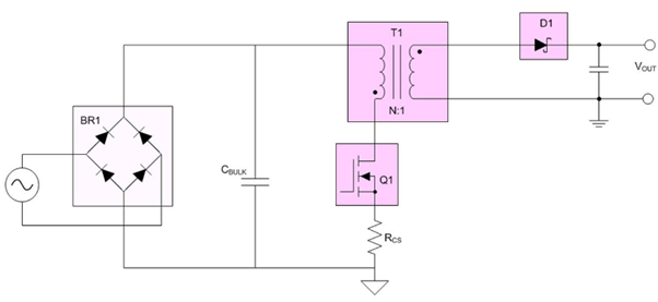
I was trying to learn how the flyback and half bridge DC-DC converter is working. For Flyback circuit, enter image description here
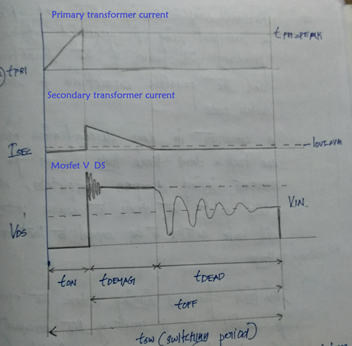
Understood output waveform is as follows. enter image description here
Keeping this understanding in mind, I was trying to analyze the Half bridge DC-DC converter working. enter image description here
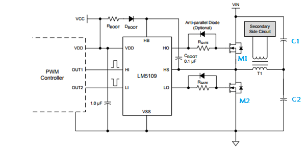
MOSFET Part number: BUK7K17-60E

Current flow as per my understanding is

For M1 is conducting: VIN -> M1 -> T1-> C2->GND

For M2 is conducting: VIN-> C1 -> T1 -> M2 -> GND

Please correct me if I am wrong.

Also, any direction to the current and mosfet drain voltage characteristics (plots) will be appreciated.

Datasheet of LM5109B: Link

I was trying to learn how the flyback and half bridge DC-DC converter is working. For Flyback circuit, enter image description here

Understood output waveform is as follows. enter image description here

Keeping this understanding in mind, I was trying to analyze the Half bridge DC-DC converter working. enter image description here

MOSFET Part number: BUK7K17-60E

Current flow as per my understanding is

For M1 is conducting: VIN -> M1 -> T1-> C2->GND

For M2 is conducting: VIN-> C1 -> T1 -> M2 -> GND

Please correct me if I am wrong.

Also, any direction to the current and mosfet drain voltage characteristics (plots) will be appreciated.

Datasheet of LM5109B: Link

Source Link
vt673
  • 897
  • 4
  • 14
  • 29

Half bridge DC-DC converter circuit analysis

I was trying to learn how the flyback and half bridge DC-DC converter is working. For Flyback circuit, enter image description here

Understood output waveform is as follows. enter image description here

Keeping this understanding in mind, I was trying to analyze the Half bridge DC-DC converter working. enter image description here

Current flow as per my understanding is

For M1 is conducting: VIN -> M1 -> T1-> C2->GND

For M2 is conducting: VIN-> C1 -> T1 -> M2 -> GND

Please correct me if I am wrong.

Also, any direction to the current and mosfet drain voltage characteristics (plots) will be appreciated.

Datasheet of LM5109B: Link