broken images fixed (click 'rendered output' or 'side-by-side' to see the difference; image retrieved via Wayback Machine); for more info, see https://gist.github.com/Glorfindel83/9d954d34385d2ac2597bbe864466259f
Source Link
Notice removed Draw attention by Brad Robinson
Bounty Ended with stevenvh's answer chosen by Brad Robinson
Added circuit diagram and description of Microbee's cassette interface
Source Link
Brad Robinson
  • 1.2k
  • 1
  • 11
  • 23
  1. The higher frequency in the RHS of the bottom signal is perfectly normal. Microbee uses 2400Hz for 1 bits, 1200Hz for 0 bits. The two signals shown are representative only and were recorded at different times.

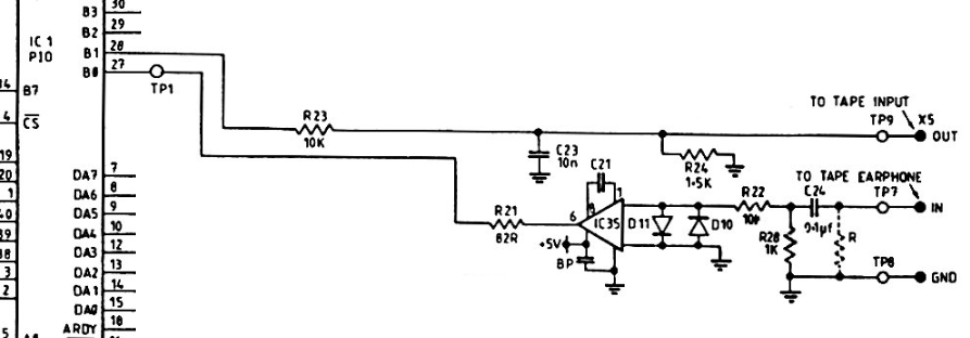
  2. In relation to where this signal was measured, from the Microbee's PIO pin 28, through the top half of the circuit shown herebelow, then through the above described voltage divider, then into the iPhone where is was recorded. ie: the voltage divider would be across OUT/GND at the far right of the circuit below.


To save referencing the other question, here's the Microbee's cassette interface circuit:

MicrobeeSchematic http://www.toptensoftware.com/fpgabee/MicrobeeCassettePortSchematic.png

and a description of it:

The cassette data output consists merely of an RC network which accepts a signal from DB1, pin 28 of the PIO. The signal is attenuated and then decoupled prior to sending it to the cassette recorder MIC input. This signal appears on pin 3 of the 5 pin DIN socket.

The cassette data input circuit is slightly more complicated. The input from pin 5 of the DIN socket passes first to an attentuator -decoupler. Following this is a CA3140 op-amp, to allow a wide range of input levels to be squared up before the signal is passed to pin 27 of the PIO, DBO. The two diodes across the inverting and non-inverting inputs to the op-amp clip any input signals greater than the diodes' forward voltage in either direction. The 47pF capacitor is required by the CMOS op-amp for precompensation.
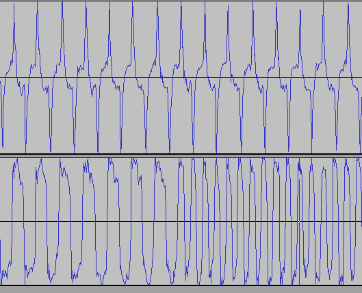
  1. The higher frequency in the RHS of the bottom signal is perfectly normal. Microbee uses 2400Hz for 1 bits, 1200Hz for 0 bits. The two signals shown are representative only and were recorded at different times.

  2. In relation to where this signal was measured, from the Microbee's PIO pin 28, through circuit shown here, then through the above described voltage divider, then into the iPhone where is was recorded.

  1. The higher frequency in the RHS of the bottom signal is perfectly normal. Microbee uses 2400Hz for 1 bits, 1200Hz for 0 bits. The two signals shown are representative only and were recorded at different times.

  2. In relation to where this signal was measured, from the Microbee's PIO pin 28, through the top half of the circuit shown below, then through the above described voltage divider, then into the iPhone where is was recorded. ie: the voltage divider would be across OUT/GND at the far right of the circuit below.


To save referencing the other question, here's the Microbee's cassette interface circuit:

MicrobeeSchematic http://www.toptensoftware.com/fpgabee/MicrobeeCassettePortSchematic.png

and a description of it:

The cassette data output consists merely of an RC network which accepts a signal from DB1, pin 28 of the PIO. The signal is attenuated and then decoupled prior to sending it to the cassette recorder MIC input. This signal appears on pin 3 of the 5 pin DIN socket.

The cassette data input circuit is slightly more complicated. The input from pin 5 of the DIN socket passes first to an attentuator -decoupler. Following this is a CA3140 op-amp, to allow a wide range of input levels to be squared up before the signal is passed to pin 27 of the PIO, DBO. The two diodes across the inverting and non-inverting inputs to the op-amp clip any input signals greater than the diodes' forward voltage in either direction. The 47pF capacitor is required by the CMOS op-amp for precompensation.
Added clarifying information
Source Link
Brad Robinson
  • 1.2k
  • 1
  • 11
  • 23
Loading
Notice added Draw attention by Brad Robinson
Bounty Started worth 50 reputation by Brad Robinson
Tweeted twitter.com/#!/StackElectronix/status/227260642015461377
Source Link
Brad Robinson
  • 1.2k
  • 1
  • 11
  • 23
Loading