This is a followup question to this one: Using an iPhone as a cassette recorder for 80's home computer
I'm trying to record from an 80's home computer (a Microbee) into an iPhone. Although I managed to get it to work, I've since learned that it's not ideal as the Microbee outputs a line-level signal, and not a microphone level as expected by the iPhone.
So I setup up a voltage divider as described here:
line-level audio into an iPhone headset jack?
This worked as far as bringing the levels down and it "sounds" right, however when played back the Microbee refuses to load the recording. (Note that loading works for recordings of other cassettes loaded onto the iPhone, so this is not a playback issue).
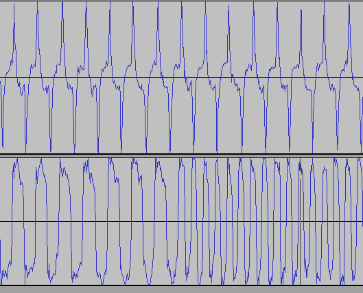
I don't have an oscilloscope, but I can look at the recorded wave form:

(source: toptensoftware.com)
The top signal is with the voltage divider, the bottom is the original line-level signal (probably saturating the iPhone's microphone preamp). As you can see it gets quite noisy around the centre. I believe the Microbee is basically looking for zero crossings when reading cassette - which would explain why it's not working.
I've tried putting various capacitors in parallel in an attempt to dampen the higher frequencies, but I don't really know what I'm doing and it made little difference.
I've also tried using a 10K pot for the voltage divider and found I could get semi-reliable recordings if I adjusted it up to just below clipping (according to the iPhone's level meter in the Voice Memos app), but for longer save files it always fails.
For reference, here's another related question including a circuit diagram and description of the Microbee's cassette interface.
Connecting an 80's style computer cassette to an FPGA
(Note that although that question is about connecting cassette to an FPGA, as far as this question is concerned I'm talking about a real Microbee)
So, my questions are:
- what else could I try to get a less noisy, microphone level signal to the iPhone.
- could this just be noise introduced by the iPhone's recording ability and/or encoding/compression? Seems unlikely.
- would using a transformer as per this: http://www.blackcatsystems.com/ipad/iPad_iPhone_iPod_Touch_Microphone_Wiring.html be a better solution. eg: does a transformer give a different frequency response than that of a voltage divider (if I had the transformer I would have tried this already).
I'd really like to get this working reliably so any other ideas appreciated.
As a side note I've also tried using Pin 6 - Left Line-in on the iPhone/iPod dock connector however haven't been able to get the device to record (it play's through the dock connector, but won't recognize it for recording). I've tried with a 2nd Gen iPod Touch, a 5th Gen iPod Nano and an iPhone 3GS with no luck... but that's another question. I only mention it in case it's suggested as a solution
Just to clarify some points raised in the answers/comments:
The higher frequency in the RHS of the bottom signal is perfectly normal. Microbee uses 2400Hz for 1 bits, 1200Hz for 0 bits. The two signals shown are representative only and were recorded at different times.
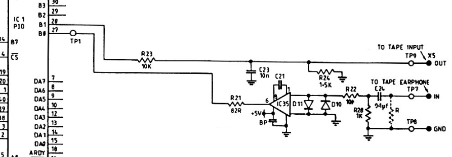
In relation to where this signal was measured, from the Microbee's PIO pin 28, through the top half of the circuit shown below, then through the above described voltage divider, then into the iPhone where is was recorded. ie: the voltage divider would be across OUT/GND at the far right of the circuit below.
To save referencing the other question, here's the Microbee's cassette interface circuit:
and a description of it:
The cassette data output consists merely of an RC network which accepts a signal from DB1, pin 28 of the PIO. The signal is attenuated and then decoupled prior to sending it to the cassette recorder MIC input. This signal appears on pin 3 of the 5 pin DIN socket.
The cassette data input circuit is slightly more complicated. The input from pin 5 of the DIN socket passes first to an attentuator -decoupler. Following this is a CA3140 op-amp, to allow a wide range of input levels to be squared up before the signal is passed to pin 27 of the PIO, DBO. The two diodes across the inverting and non-inverting inputs to the op-amp clip any input signals greater than the diodes' forward voltage in either direction. The 47pF capacitor is required by the CMOS op-amp for precompensation.

