Bumped by Community user

sizing Sizing zener and resistor for solenoid flyback

I am trying to drive a vibratory pump from a 220v220 V boost converter (the common '150W150 W DC-/AC 12V To 220V12 V to 220 V boost converter'converter found on ebay) and a mosfetMOSFET switched by an arduinoArduino/optoisolator at 50hz50 Hz. The pump can be considered a solenoid and a video description is available here..

I arbitrarily chose a 2n60 mosfet2N60 MOSFET because it was the firstfirst one I found that was cheap and had a 600v600 V breakdown voltage. I assume there is a better and cheaper mosfetMOSFET I could have chosen. (feel free to suggest a better choice).

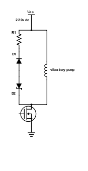
If I can trust some of the blogs I have read, the pump has a measured inductance of 854mH854 mH and a series resistance of 165Ω165 Ω. The power draw is rated as 53 watts. I am told that a simple flyback diode will reduce pump pressure and that a diode plus a 10w 220Ω resister10 W 220 Ω resistor will allow full pressure although the resistor will get a little hot. I am thinking that a zener will improve the power dissipation but I am not sure how to choose good values for the resistor and zener.

pump flyback  circuit

I am trying to keep the circuit cheap, physically small, and not outrageously hot for a closed box.

Is there a better way for me to do this? (II assume that a 600v600 V breakdown voltage still needs some flyback protection).

sizing zener and resistor for solenoid flyback

I am trying to drive a vibratory pump from a 220v boost converter (the common '150W DC-AC 12V To 220V boost converter' found on ebay) and a mosfet switched by an arduino/optoisolator at 50hz. The pump can be considered a solenoid and a video description is available here. I arbitrarily chose a 2n60 mosfet because it was the first one I found that was cheap and had a 600v breakdown voltage. I assume there is a better and cheaper mosfet I could have chosen. (feel free to suggest a better choice)

If I can trust some of the blogs I have read, the pump has a measured inductance of 854mH and a series resistance of 165Ω. The power draw is rated as 53 watts. I am told that a simple flyback diode will reduce pump pressure and that a diode plus a 10w 220Ω resister will allow full pressure although the resistor will get a little hot. I am thinking that a zener will improve the power dissipation but I am not sure how to choose good values for the resistor and zener.

pump flyback  circuit

I am trying to keep the circuit cheap, physically small, and not outrageously hot for a closed box.

Is there a better way for me to do this? (I assume that a 600v breakdown voltage still needs some flyback protection)

Sizing zener and resistor for solenoid flyback

I am trying to drive a vibratory pump from a 220 V boost converter (the common 150 W DC/AC 12 V to 220 V boost converter found on ebay) and a MOSFET switched by an Arduino/optoisolator at 50 Hz. The pump can be considered a solenoid and a video description is available here.

I arbitrarily chose a 2N60 MOSFET because it was the first one I found that was cheap and had a 600 V breakdown voltage. I assume there is a better and cheaper MOSFET I could have chosen (feel free to suggest a better choice).

If I can trust some of the blogs I have read, the pump has a measured inductance of 854 mH and a series resistance of 165 Ω. The power draw is rated as 53 watts. I am told that a simple flyback diode will reduce pump pressure and that a diode plus a 10 W 220 Ω resistor will allow full pressure although the resistor will get a little hot. I am thinking that a zener will improve the power dissipation but I am not sure how to choose good values for the resistor and zener.

pump flyback  circuit

I am trying to keep the circuit cheap, physically small, and not outrageously hot for a closed box.

Is there a better way for me to do this? I assume that a 600 V breakdown voltage still needs some flyback protection.

Source Link

sizing zener and resistor for solenoid flyback

I am trying to drive a vibratory pump from a 220v boost converter (the common '150W DC-AC 12V To 220V boost converter' found on ebay) and a mosfet switched by an arduino/optoisolator at 50hz. The pump can be considered a solenoid and a video description is available here. I arbitrarily chose a 2n60 mosfet because it was the first one I found that was cheap and had a 600v breakdown voltage. I assume there is a better and cheaper mosfet I could have chosen. (feel free to suggest a better choice)

If I can trust some of the blogs I have read, the pump has a measured inductance of 854mH and a series resistance of 165Ω. The power draw is rated as 53 watts. I am told that a simple flyback diode will reduce pump pressure and that a diode plus a 10w 220Ω resister will allow full pressure although the resistor will get a little hot. I am thinking that a zener will improve the power dissipation but I am not sure how to choose good values for the resistor and zener.

pump flyback  circuit

I am trying to keep the circuit cheap, physically small, and not outrageously hot for a closed box.

Is there a better way for me to do this? (I assume that a 600v breakdown voltage still needs some flyback protection)