To add the relevant information from the link posted by Brian O'Regan as full answer:
The document refers to three common/popular circuits for digital LED drives:
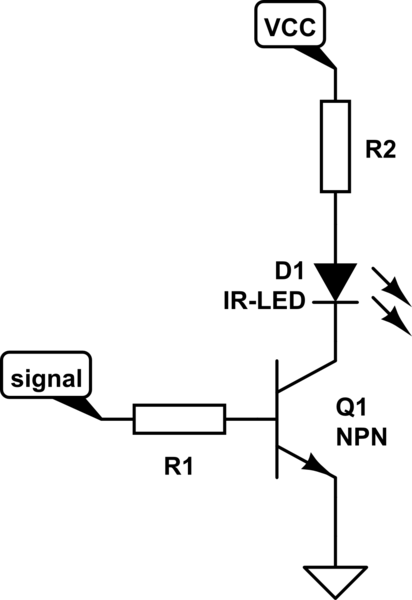
- Series drive
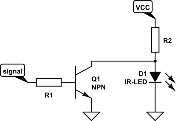
- Shunt
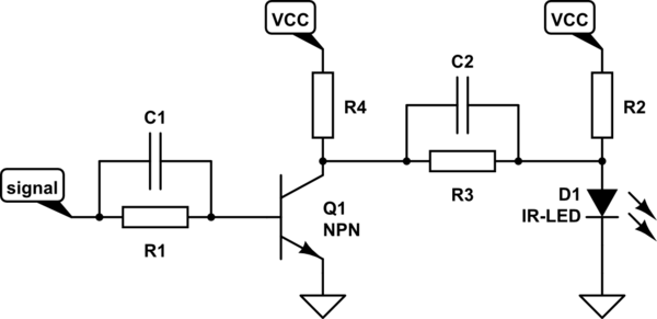
- Shunt with over and under-drive
1. Series

simulate this circuit – Schematic created using CircuitLab
- Q1 directly switches the LED
Pro: Low average power supply current
Con: Low speed (< 30-50 Mb/s)
2. Shunt

- Q1 shunts the LED - so a quick discharge == fast turn-off time
Pro: Higher speed (several times faster then 1)
Con: Higher power dissipation (circuit draws more current when LED than when LED is on!)
3. Shunt with Over & Under Drive

extends 2.
- C1 increasesdecreases the switching times of Q1
- R3, R4 and C2 provide over-drive at turn-on and under-drive at turn-off
- typical RC time constant for R3 + C2 == rise/fall time of LED
Pro: higher resulting speeds than 2.
Con: carefully chosen values needed - otherwise destructive
summary:
- For high-performance LEDs and driver design, optical rise times can be as short as 1.5ns.
- Most LEDs have slower turn-off times.
- Here with careful design 2.5ns optical turn-off time can be reached.
- It is often a good idea to have a small (few percent of peak drive current) pre-bias current to improve dynamic response and so the LED never gets reverse biased.
With all these concepts, operating speeds to about 270 Mb/s can be reached for production ready setups.
All this information is only sourced from the linked document. No self experimentation has been done.
I felt that this was a too big an edit of the original answer; if that's wrong I am happy to move the information over into an edit.
