24
\$\begingroup\$

I need to modulate a LED quickly (multi-megahertz range) on/off. It's a high-power LED. I have had some trouble locating any well-known methods to do this. Simply switching the voltage with a FET turns on the LED quickly but the fall-time will suffer, and to solve that, I guess there are some different solutions, for example maybe switching in a reverse bias for a short while? Any ideas?

I think the underlying problem with the turn-off is that the charge-carriers make the p-n junction act a bit like an inductor in that the current will keep on going for a short while after turning off the voltage gradient, but I haven't found any reference on this.

I know that a laser-diode can be modulated much faster.

EDIT: since this question has a lot of views, let me add some context - the application for this was a 3D camera using a time-of-flight CMOS sensor. Essentially, you send out light, it bounces on the scene to be imaged, and the image sensor can discern the phase difference between the sent light and received light. Faster and deeper modulation means better resolution and less noise in the 3D image. In this particular application, 20 MHz was the target modulation rate.

\$\endgroup\$
3
  • \$\begingroup\$ lasers are by no means comparable to LEDs (except that both emit light). The fastest laser yet is more than \$10^{9}\$ times faster than a LED. \$\endgroup\$
    – stevenvh
    Commented Jun 23, 2011 at 0:17
  • 4
    \$\begingroup\$ @stevenvh: yes, that qualifies as "much faster" right? ;) \$\endgroup\$ Commented Jun 23, 2011 at 8:04
  • 4
    \$\begingroup\$ Why can laser diodes be modulated faster than regular light-emitting diodes? \$\endgroup\$
    – endolith
    Commented Sep 1, 2011 at 5:26

9 Answers 9

12
\$\begingroup\$

If you are trying to send data this way, don't try to modulate it 0%-100%. Go 10%-90%, this will be way faster.

To switch it off rapidly, you need 2 transistors in push-pull configuration, PNP+NPN or N-MOSFET + P-MOSFET, so that in 'off' state LED will be shorted to ground. Achieving high speed with BJT would be easier.

If you need to go over 1-5Mhz, you will need to add anti-saturation Schottky diodes.

Another thing to try is bridge circuit out of 4 BJT's - it will eliminate remaining charge in LED even faster (as LED will be reverse biased in off state), but I haven't tried that. Some LED's might die if reverse biased too much.

\$\endgroup\$
4
  • \$\begingroup\$ thanks for your answer, it was something like this I was experimenting with! additional question: what do you mean with 0-100 being slower than 10-90%? obviously the total rise/fall time will be slower, but if the rise/fall edge speed is the same, the eye area increases in total, and helps my modulation. why is a BJT-setup faster by the way? the lack of FET gate charge modulation? \$\endgroup\$ Commented Jun 23, 2011 at 8:04
  • 2
    \$\begingroup\$ Yes, driving MOSFETs at high speed is hard. About the 10-90 thing - rise from switch-off is slower than from 10% of brightness. So due to that in DVD-RW drives for example this approach is used - laser is never switched off, but in "off" state it's power is significantly lower. \$\endgroup\$ Commented Jun 23, 2011 at 8:29
  • 2
    \$\begingroup\$ Also, seems that I was wrong about 90% - disregard that, 2 cases are 0-100%, and 10-100%, not 0-100 and 10-90. \$\endgroup\$ Commented Jun 23, 2011 at 8:32
  • \$\begingroup\$ @BarsMonster You should edit your original comment with a fix for the 10-100% thing \$\endgroup\$ Commented Oct 22, 2019 at 18:34
6
\$\begingroup\$

LEDs themselves take a little time to turn off, but I think a few MHz is still possible.

It sounds like your problem is the off time of the transistor used to switch the LED. Try driving the LED from the emitter instead of the collector. Logic output drives base of NPN directly, collector connected to supply, emitter to resistor, then to LED, then to ground. Since the transistor never saturates, it should turn off quickly. The base is being actively forced to a low voltage, which should also help turn it off quickly.

\$\endgroup\$
4
  • \$\begingroup\$ yes I'm at least going to try with a FET with a faster specified off-time - although simply moving the gate-charge is a delimiting factor as well so buffers are needed. do you think a BJT would actually work better in this case? I'm pulling 2A... \$\endgroup\$ Commented Jun 22, 2011 at 21:14
  • \$\begingroup\$ Are you implying that because it doesn't saturate, the slew rate has less effect on the switching time since \$\Delta t= \left ( slew rate \right ) * \Delta V \$ ? \$\endgroup\$
    – NickHalden
    Commented Jun 22, 2011 at 23:17
  • \$\begingroup\$ <strike>would one of those emitter switched bipolar transistors we saw the other day help perphaps? I remember they seemed to have faster switching times than normal NPN bjts</strike> Nevermind I guess they were for high voltage applications \$\endgroup\$
    – NickHalden
    Commented Jun 22, 2011 at 23:21
  • \$\begingroup\$ @JGord: I wasn't really talking about dV/dt. In this case we are switching current, not voltage. A saturated BJT takes a while to turn off because there are lots of extra minority carriers in the base. They hang around after the base current is shut off, causing conduction until eventually used up. A BJT never saturates in emitter follower mode, so can turn off quickly. No, a emitter switched bipolar would not be appropriate here. \$\endgroup\$ Commented Jun 23, 2011 at 12:27
6
\$\begingroup\$

To add the relevant information from the link posted by Brian O'Regan as full answer:

The document refers to three common/popular circuits for digital LED drives:

  1. Series drive
  2. Shunt
  3. Shunt with over and under-drive

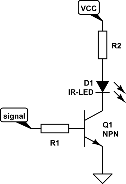
1. Series

schematic

simulate this circuit – Schematic created using CircuitLab

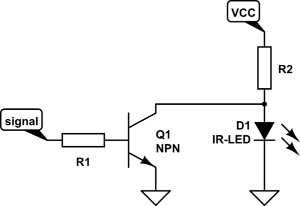
  • Q1 directly switches the LED

Pro: Low average power supply current
Con: Low speed (< 30-50 Mb/s)

2. Shunt

schematic

simulate this circuit

  • Q1 shunts the LED - so a quick discharge == fast turn-off time

Pro: Higher speed (several times faster then 1)
Con: Higher power dissipation (circuit draws more current when LED than when LED is on!)

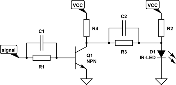
3. Shunt with Over & Under Drive

schematic

simulate this circuit

extends 2.

  • C1 decreases the switching times of Q1
  • R3, R4 and C2 provide over-drive at turn-on and under-drive at turn-off
  • typical RC time constant for R3 + C2 == rise/fall time of LED

Pro: higher resulting speeds than 2.
Con: carefully chosen values needed - otherwise destructive

summary:

  • For high-performance LEDs and driver design, optical rise times can be as short as 1.5ns.
  • Most LEDs have slower turn-off times.
  • Here with careful design 2.5ns optical turn-off time can be reached.
  • It is often a good idea to have a small (few percent of peak drive current) pre-bias current to improve dynamic response and so the LED never gets reverse biased.

With all these concepts, operating speeds to about 270 Mb/s can be reached for production ready setups.


All this information is only sourced from the linked document. No self experimentation has been done.


I felt that this was a too big an edit of the original answer; if that's wrong I am happy to move the information over into an edit.

\$\endgroup\$
4
\$\begingroup\$

there is a simple circuit for fast LED switching on this website. http://www.fiber-optics.info/articles/light-emitting_diode_led Haven't tried it but I am working on the same problem. need fastest turn off time after continuous operation

\$\endgroup\$
1
  • 4
    \$\begingroup\$ Can you bring some of the linked information to your answer? When that link dies your answer becomes useless. \$\endgroup\$
    – stevenvh
    Commented Oct 1, 2012 at 9:48
3
\$\begingroup\$

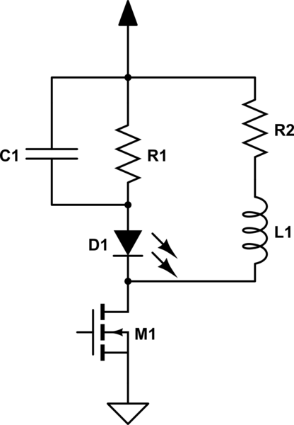
I wanted to add this circuit which I saw in a paper. It has both over drive and under drive but I don't know how it compares to 3. Shunt with Over & Under Drive in Stefan Kruger's answer though. Seems like it should be lower power...at least when off. Again, values have to be carefully so the positive current peaking on the charge and the negative current peaking on the discharge (and their associated voltage spike applied to the diode) don't fry it, though you might be able to place a TVS in parallel to protect the LED and make component selection critical without sacrificing speed.

I have yet to use this circuit but you might be able to improve turn-on speed with a large bias resistor in parallel with the MOSFET so that the LED is biased when off. However, the MOSFET leakage current might be sufficient for this or it might be unnecessary with the current peaking. I suppose you could also change it to be an emitter or source follower to prevent saturation if the transistor speed ends up somehow being the limiting factor.

schematic

simulate this circuit – Schematic created using CircuitLab

\$\endgroup\$
2
  • \$\begingroup\$ I like the idea. I think it would be possible to omit L1 while keeping R2, then the turn off current would be provided by C1, albiet with less strength \$\endgroup\$ Commented Feb 18, 2023 at 20:04
  • \$\begingroup\$ @EmbeddedSoftwareEngineer It would take less design caution for sure. Mis-sizing L1 could blow the LED. \$\endgroup\$
    – DKNguyen
    Commented Feb 18, 2023 at 21:19
2
\$\begingroup\$

I made an avalanche transistor circuit with the Zetex FMMT 413, 415, or 417 TA. Instead of a capacitor, I used a 50 Ohm coax cable like in a Blumlein circuit. With this I drove a small SMT green LED and got a ~7 ns rise time and a pulse width of ~10 ns (determined by the length of the coax cable for the Blumlein circuit). You need a HV power supply for the avalanche transistor.

\$\endgroup\$
2
  • 4
    \$\begingroup\$ A schematic would help make your answer more useful. Until you have a bit more rep, you can upload it to a free image hosting site and include a link in your answer. Someone will then edit your answer to put the image inline. \$\endgroup\$
    – The Photon
    Commented Jun 20, 2014 at 1:26
  • 1
    \$\begingroup\$ Also, greetings and salutations are not used here. An icon with your user name is automatically added to all your posts. If you want to share your contact information, you can put it on your user page. \$\endgroup\$
    – The Photon
    Commented Jun 20, 2014 at 1:28
1
\$\begingroup\$

Have you considered using a "transistor driver" to drive your LED? (Or perhaps considered using a "transistor driver" the way it was intended to be used, to drive a transistor -- that then drives your LED?)

I'm talking about devices such as the Microchip MCP14628, the Texas Instruments TPS28226, etc., available at my favorite electronic supply websites, all of which the datasheet claims can switch a highly capacitive load in 10 ns. (Hopefully your LED is much less capacitive and so those chips can switch it faster).

p.s.: the datasheet for each transistor drivers gives a big-sounding number for "peak power". That number is only valid for very short pulses. LEDs often have a similar "peak power" rating about 4 times the continuous-power rating. I hear that most optical communication systems are carefully designed such the system turns the LED or laser on for at most one or two bit times before turning it off and letting it cool -- such as one-of-two encoding aka Manchester code, and one-of-four encoding aka PPM.

I hear rumors that some IrDA devices can communicate at 16 Mbit/s, 96 Mbit/s, or 1 Gbit/s. Is this close enough to what you want to do that you can buy something off the shelf? Or perhaps buy something off the shelf, crack it open, and make relatively minor modifications?

\$\endgroup\$
0
\$\begingroup\$

I don't know what your application is, but could this range of high brightness LED drivers be of interest / use?

http://www.maxim-ic.com/datasheet/index.mvp/id/5274

There are other similar ones as well.

\$\endgroup\$
1
  • 2
    \$\begingroup\$ thanks, but the switchmode current supplies are too slow to control a modulated LED unless it is done as a pure average control - for example, if you modulate on/off with a 50/50 dutycycle, you can use the current driver to provide the average current. but for my application I don't really need a super-stable current, it is the actual on/off-switching which is the important thing and this has to be added to the mentioned chip anyway externally. the problem here is mainly that of LED and FET/BJT physics, not current control (a resistor in series would do). \$\endgroup\$ Commented Jun 22, 2011 at 23:03
0
\$\begingroup\$

I've looked into fast pulses before, and we ended up implementing something like the circuit in this paper (better quality figures in a related powerpoint). This is effectively a current-pulse-shaping circuit, and you'll find more if you search on "nanosecond pulsed LEDs"

\$\endgroup\$

Your Answer

By clicking “Post Your Answer”, you agree to our terms of service and acknowledge you have read our privacy policy.

Not the answer you're looking for? Browse other questions tagged or ask your own question.