added 14 characters in body
Source Link
Marcus Müller
  • 100.1k
  • 5
  • 141
  • 262

I need to trigger remote devices through their hardware trigger inputs simultaneously (within 1 ms) from a single trigger source which has a timer output. So basically the 0/5V pulse-train at around 40Hz will trigger many devices simultaneously. The distance between the trigger source and a device is varying between 5 meters up to 200 meters. Total number of devices can be around 10.

I'm planning to use the following scheme:
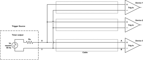
schematic

simulate this circuit – Schematic created using CircuitLab

I can add an opamp buffer just after the the trigger source that is not a problem. But I really want to minimize extra components or electronics in between unless it is ready made modules ect. in the market that I can buy.

Is there any problem to use this scheme in this case?

One of my worry is whether I need a termination resistor at the device trigger inputs, because the sharp rising edges of the pulses can be an issue for ringing?

Another worry is the false triggering due to glitches due to interference ect. RC filters needed at the device inputs? (I plan to use coaxial cables)

Or is there another robust way to implement for this scenario?

I need to trigger remote devices through their hardware trigger inputs simultaneously from a single trigger source which has a timer output. So basically the 0/5V pulse-train at around 40Hz will trigger many devices simultaneously. The distance between the trigger source and a device is varying between 5 meters up to 200 meters. Total number of devices can be around 10.

I'm planning to use the following scheme:

schematic

simulate this circuit – Schematic created using CircuitLab

I can add an opamp buffer just after the the trigger source that is not a problem. But I really want to minimize extra components or electronics in between unless it is ready made modules ect. in the market that I can buy.

Is there any problem to use this scheme in this case?

One of my worry is whether I need a termination resistor at the device trigger inputs, because the sharp rising edges of the pulses can be an issue for ringing?

Another worry is the false triggering due to glitches due to interference ect. RC filters needed at the device inputs? (I plan to use coaxial cables)

Or is there another robust way to implement for this scenario?

I need to trigger remote devices through their hardware trigger inputs simultaneously (within 1 ms) from a single trigger source which has a timer output. So basically the 0/5V pulse-train at around 40Hz will trigger many devices simultaneously. The distance between the trigger source and a device is varying between 5 meters up to 200 meters. Total number of devices can be around 10.

I'm planning to use the following scheme:

schematic

simulate this circuit – Schematic created using CircuitLab

I can add an opamp buffer just after the the trigger source that is not a problem. But I really want to minimize extra components or electronics in between unless it is ready made modules ect. in the market that I can buy.

Is there any problem to use this scheme in this case?

One of my worry is whether I need a termination resistor at the device trigger inputs, because the sharp rising edges of the pulses can be an issue for ringing?

Another worry is the false triggering due to glitches due to interference ect. RC filters needed at the device inputs? (I plan to use coaxial cables)

Or is there another robust way to implement for this scenario?

Source Link
floppy380
  • 1.9k
  • 7
  • 41
  • 79

Hardware triggering multiple devices from a single source for long distances

I need to trigger remote devices through their hardware trigger inputs simultaneously from a single trigger source which has a timer output. So basically the 0/5V pulse-train at around 40Hz will trigger many devices simultaneously. The distance between the trigger source and a device is varying between 5 meters up to 200 meters. Total number of devices can be around 10.

I'm planning to use the following scheme:

schematic

simulate this circuit – Schematic created using CircuitLab

I can add an opamp buffer just after the the trigger source that is not a problem. But I really want to minimize extra components or electronics in between unless it is ready made modules ect. in the market that I can buy.

Is there any problem to use this scheme in this case?

One of my worry is whether I need a termination resistor at the device trigger inputs, because the sharp rising edges of the pulses can be an issue for ringing?

Another worry is the false triggering due to glitches due to interference ect. RC filters needed at the device inputs? (I plan to use coaxial cables)

Or is there another robust way to implement for this scenario?