Tweeted twitter.com/StackElectronix/status/1014747709243363328

I am in a bit of a pickle. If anyone could help/has any ideas I will be very grateful - am aware this post is pretty long but thought if anyone was clever enough to know it would be you guys. If anyone needs more information/has ideas then I'm also listening! Thank you.

Have a specialist bit of kit which uses proximity sensors and would dearly like to be able to replace sensors on it with the same model. However, I am unable to ID the chip and manufacturer of product will not help. Therefore - does anyone know what chip this might be? The chip senses reflectance from a person from about 1cm to closer.

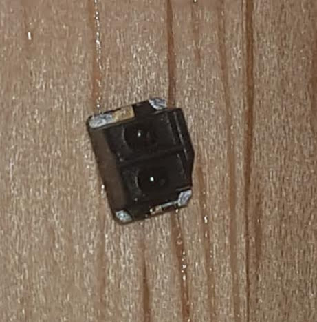
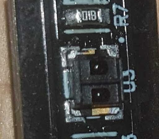
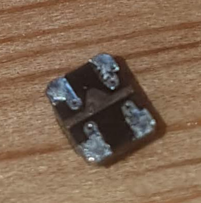
Visually inspecting the chip it consists of an LED and a sensor, seperatedseparated by some dividing plastic. On the underside, it has 4 pads, with 4 microvias.   

enter image description here    enter image description here    enter image description hereInitially

Initially it looks like the chip was mounted on a small PCB but I think this is an integral part of the chip - or at least I have been unable to seperateseparate it with hot air. No markings anywhere other than an arrow of copper to indicate direction, on underside, as well as a slightly larger pad on the top layer of the "pcb" to again indicate LED.

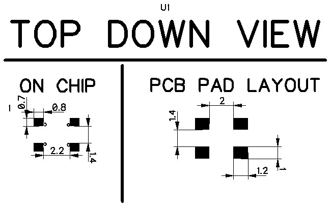
On PCB layout it is measured as shown.   

enter image description here Pad

Pad layout on the chip is pretty similar. I was unable to measure the microvias so haven't included dimensions.

Pin layout is (from pin1 marked on PCB layout moving clockwise):

  1. Phototransistor/diode Anode

    Phototransistor/diode Anode
  2. IR LED Anode

    IR LED Anode
  3. IR LED Cathode

    IR LED Cathode
  4. Phototransistor/diode Cathode

    Phototransistor/diode Cathode

The phototransistor/diode is operating in reverse bias. Vcc is connected to pins 2 + 4. Pin 3 connected via current limiting resistor (100 ohm) to digital ground. Pin 4 is run to analog ground via 1k resistor w cap in parallel for noise reduction (standard voltage divider). It (pin 4) also runs to an ADC where measurement is taken. Vcc is approx 3.6V.

I don't have a spectrometre so am unable to confirm what wavelength of light is but I assume it's IR as it is not visible.

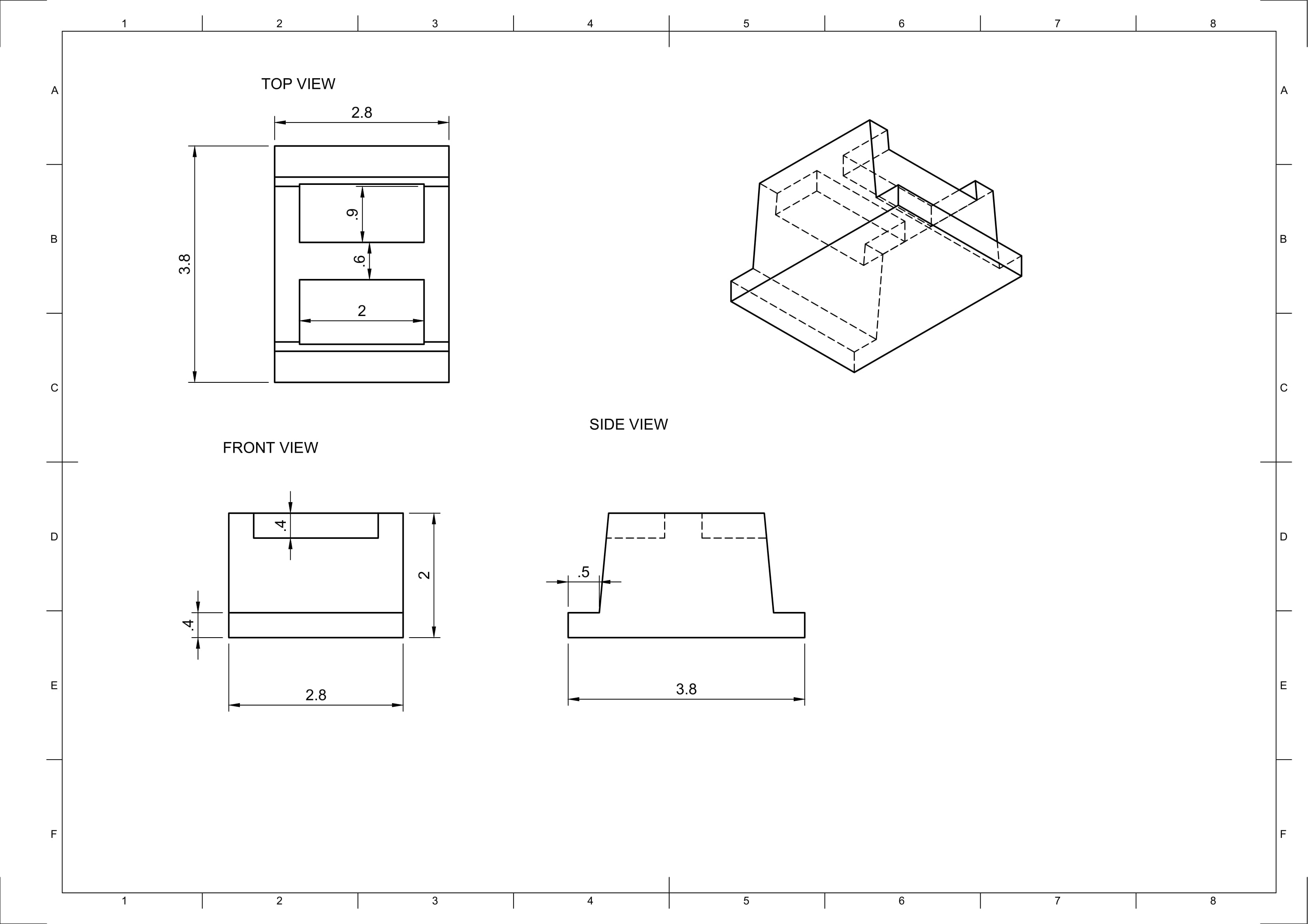
I have sketched the dimensions here -   

enter image description hereI

I modelled it in fusion though my calipers are fairly budget so the accuracy may be slightly off(+-0.1mm). https://a360.co/2Kkbv5k

Thanks for the help!

I am in a bit of a pickle. If anyone could help/has any ideas I will be very grateful - am aware this post is pretty long but thought if anyone was clever enough to know it would be you guys. If anyone needs more information/has ideas then I'm also listening! Thank you.

Have a specialist bit of kit which uses proximity sensors and would dearly like to be able to replace sensors on it with the same model. However, I am unable to ID the chip and manufacturer of product will not help. Therefore - does anyone know what chip this might be? The chip senses reflectance from a person from about 1cm to closer.

Visually inspecting the chip it consists of an LED and a sensor, seperated by some dividing plastic. On the underside, it has 4 pads, with 4 microvias.  enter image description here  enter image description here  enter image description hereInitially it looks like the chip was mounted on a small PCB but I think this is an integral part of the chip - or at least I have been unable to seperate it with hot air. No markings anywhere other than an arrow of copper to indicate direction, on underside, as well as a slightly larger pad on the top layer of the "pcb" to again indicate LED.

On PCB layout it is measured as shown.  enter image description here Pad layout on the chip is pretty similar. I was unable to measure the microvias so haven't included dimensions.

Pin layout is (from pin1 marked on PCB layout moving clockwise):

  1. Phototransistor/diode Anode

  2. IR LED Anode

  3. IR LED Cathode

  4. Phototransistor/diode Cathode

The phototransistor/diode is operating in reverse bias. Vcc is connected to pins 2 + 4. Pin 3 connected via current limiting resistor (100 ohm) to digital ground. Pin 4 is run to analog ground via 1k resistor w cap in parallel for noise reduction (standard voltage divider). It (pin 4) also runs to an ADC where measurement is taken. Vcc is approx 3.6V.

I don't have a spectrometre so am unable to confirm what wavelength of light is but I assume it's IR as it is not visible.

I have sketched the dimensions here -  enter image description hereI modelled it in fusion though my calipers are fairly budget so the accuracy may be slightly off(+-0.1mm). https://a360.co/2Kkbv5k

Thanks for the help!
I am in a bit of a pickle. If anyone could help/has any ideas I will be very grateful - am aware this post is pretty long but thought if anyone was clever enough to know it would be you guys. If anyone needs more information/has ideas then I'm also listening! Thank you.

Have a specialist bit of kit which uses proximity sensors and would dearly like to be able to replace sensors on it with the same model. However, I am unable to ID the chip and manufacturer of product will not help. Therefore - does anyone know what chip this might be? The chip senses reflectance from a person from about 1cm to closer.

Visually inspecting the chip it consists of an LED and a sensor, separated by some dividing plastic. On the underside, it has 4 pads, with 4 microvias. 

enter image description here  enter image description here  enter image description here

Initially it looks like the chip was mounted on a small PCB but I think this is an integral part of the chip - or at least I have been unable to separate it with hot air. No markings anywhere other than an arrow of copper to indicate direction, on underside, as well as a slightly larger pad on the top layer of the "pcb" to again indicate LED.

On PCB layout it is measured as shown. 

enter image description here

Pad layout on the chip is pretty similar. I was unable to measure the microvias so haven't included dimensions.

Pin layout is (from pin1 marked on PCB layout moving clockwise):

  1. Phototransistor/diode Anode
  2. IR LED Anode
  3. IR LED Cathode
  4. Phototransistor/diode Cathode

The phototransistor/diode is operating in reverse bias. Vcc is connected to pins 2 + 4. Pin 3 connected via current limiting resistor (100 ohm) to digital ground. Pin 4 is run to analog ground via 1k resistor w cap in parallel for noise reduction (standard voltage divider). It (pin 4) also runs to an ADC where measurement is taken. Vcc is approx 3.6V.

I don't have a spectrometre so am unable to confirm what wavelength of light is but I assume it's IR as it is not visible.

I have sketched the dimensions here - 

enter image description here

I modelled it in fusion though my calipers are fairly budget so the accuracy may be slightly off(+-0.1mm). https://a360.co/2Kkbv5k

Thanks for the help!
Source Link

What is this? Identifying Proximity Sensor Chip (IR)

I am in a bit of a pickle. If anyone could help/has any ideas I will be very grateful - am aware this post is pretty long but thought if anyone was clever enough to know it would be you guys. If anyone needs more information/has ideas then I'm also listening! Thank you.

Have a specialist bit of kit which uses proximity sensors and would dearly like to be able to replace sensors on it with the same model. However, I am unable to ID the chip and manufacturer of product will not help. Therefore - does anyone know what chip this might be? The chip senses reflectance from a person from about 1cm to closer.

Visually inspecting the chip it consists of an LED and a sensor, seperated by some dividing plastic. On the underside, it has 4 pads, with 4 microvias. enter image description here enter image description here enter image description hereInitially it looks like the chip was mounted on a small PCB but I think this is an integral part of the chip - or at least I have been unable to seperate it with hot air. No markings anywhere other than an arrow of copper to indicate direction, on underside, as well as a slightly larger pad on the top layer of the "pcb" to again indicate LED.

On PCB layout it is measured as shown. enter image description here Pad layout on the chip is pretty similar. I was unable to measure the microvias so haven't included dimensions.

Pin layout is (from pin1 marked on PCB layout moving clockwise):

  1. Phototransistor/diode Anode

  2. IR LED Anode

  3. IR LED Cathode

  4. Phototransistor/diode Cathode

The phototransistor/diode is operating in reverse bias. Vcc is connected to pins 2 + 4. Pin 3 connected via current limiting resistor (100 ohm) to digital ground. Pin 4 is run to analog ground via 1k resistor w cap in parallel for noise reduction (standard voltage divider). It (pin 4) also runs to an ADC where measurement is taken. Vcc is approx 3.6V.

I don't have a spectrometre so am unable to confirm what wavelength of light is but I assume it's IR as it is not visible.

I have sketched the dimensions here - enter image description hereI modelled it in fusion though my calipers are fairly budget so the accuracy may be slightly off(+-0.1mm). https://a360.co/2Kkbv5k

Thanks for the help!