Add more package information
Source Link

part identification question here. It comes from an Xfinity XR11 Remote. It’s used to detect acceleration when picking up the remote.
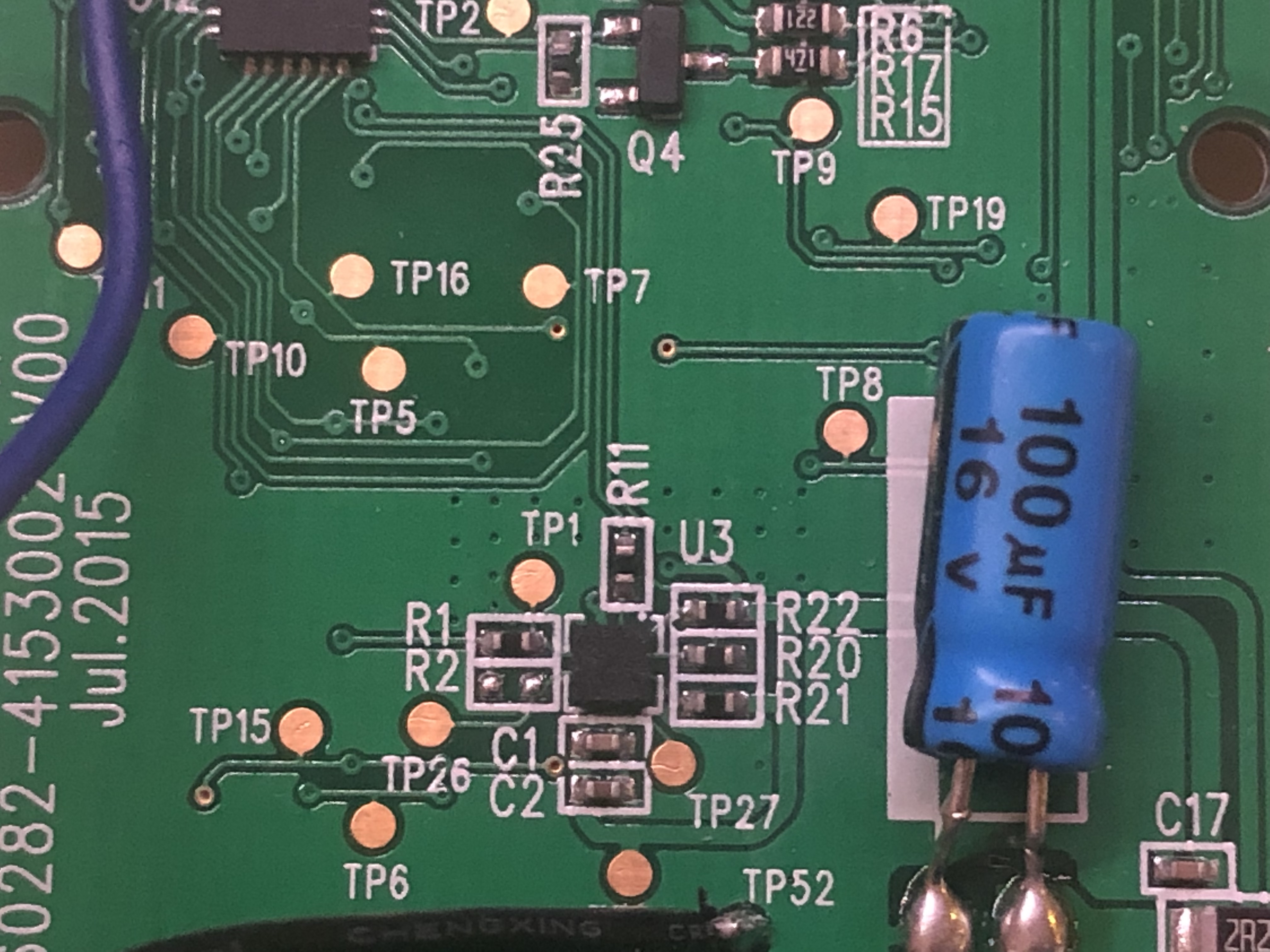
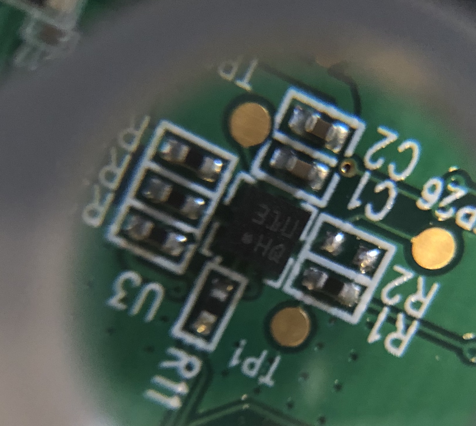
Position on board Package Closeup

The footprint and part/trace placement heavily matches what I’d expect for an STM accelerometer but the register map just doesn’t fit. Specifically one of these.

The package reads 31UHQ and is a 2mmx2mm LGA package. It seems that the 4x3 pin layout has a standard pin configuration of two interrupt outputs and I2C/SPI pin locations. 

It has registers starting at 0x00 and some of the reads and writes I see from a logic analyzer are to addresses that the datasheet claims are “reserved”. For example, bits 0, 1, and 2 on register 0x17 enable the X, Y, and Z axis. I can provide a full register dump if needed.

If it helps, here are the ins and outs. All resistors are 0ohm bridges.

  • R11 = SCL
  • R20 = SDA
  • TP50 = VCC (2v5)
  • TP1 = Interrupt (not sure if INT0 or INT1)
  • TP26 = Unknown
  • TP27 = Unknown

Start-up sequence: (Op, Reg, Data)

  1. W 17 07
  2. W 19 02
  3. W 25 04
  4. W 26 06
  5. W 36 07
  6. W 20 08

part identification question here. It comes from an Xfinity XR11 Remote. It’s used to detect acceleration when picking up the remote.

Position on board Package Closeup

The footprint and part/trace placement heavily matches what I’d expect for an STM accelerometer but the register map just doesn’t fit. Specifically one of these.

The package reads 31UHQ. It has registers starting at 0x00 and some of the reads and writes I see from a logic analyzer are to addresses that the datasheet claims are “reserved”. For example, bits 0, 1, and 2 on register 0x17 enable the X, Y, and Z axis. I can provide a full register dump if needed.

If it helps, here are the ins and outs. All resistors are 0ohm bridges.

  • R11 = SCL
  • R20 = SDA
  • TP50 = VCC (2v5)
  • TP1 = Interrupt (not sure if INT0 or INT1)
  • TP26 = Unknown
  • TP27 = Unknown

Start-up sequence: (Op, Reg, Data)

  1. W 17 07
  2. W 19 02
  3. W 25 04
  4. W 26 06
  5. W 36 07
  6. W 20 08

part identification question here. It comes from an Xfinity XR11 Remote. It’s used to detect acceleration when picking up the remote.

Position on board Package Closeup

The footprint and part/trace placement heavily matches what I’d expect for an STM accelerometer but the register map just doesn’t fit. Specifically one of these.

The package reads 31UHQ and is a 2mmx2mm LGA package. It seems that the 4x3 pin layout has a standard pin configuration of two interrupt outputs and I2C/SPI pin locations. 

It has registers starting at 0x00 and some of the reads and writes I see from a logic analyzer are to addresses that the datasheet claims are “reserved”. For example, bits 0, 1, and 2 on register 0x17 enable the X, Y, and Z axis. I can provide a full register dump if needed.

If it helps, here are the ins and outs. All resistors are 0ohm bridges.

  • R11 = SCL
  • R20 = SDA
  • TP50 = VCC (2v5)
  • TP1 = Interrupt (not sure if INT0 or INT1)
  • TP26 = Unknown
  • TP27 = Unknown

Start-up sequence: (Op, Reg, Data)

  1. W 17 07
  2. W 19 02
  3. W 25 04
  4. W 26 06
  5. W 36 07
  6. W 20 08
Tweeted twitter.com/StackElectronix/status/1078667007241977856
Add startup sequence
Source Link

part identification question here. It comes from an Xfinity XR11 Remote. It’s used to detect acceleration when picking up the remote.

Position on board Package Closeup

The footprint and part/trace placement heavily matches what I’d expect for an STM accelerometer but the register map just doesn’t fit. Specifically one of these.

The package reads 31UHQ. It has registers starting at 0x00 and some of the reads and writes I see from a logic analyzer are to addresses that the datasheet claims are “reserved”. For example, bits 0, 1, and 2 on register 0x17 enable the X, Y, and Z axis. I can provide a full register dump if needed.

If it helps, here are the ins and outs. All resistors are 0ohm bridges.

  • R11 = SCL
  • R20 = SDA
  • TP50 = VCC (2v5)
  • TP1 = Interrupt (not sure if INT0 or INT1)
  • TP26 = Unknown
  • TP27 = Unknown

Start-up sequence: (Op, Reg, Data)

  1. W 17 07
  2. W 19 02
  3. W 25 04
  4. W 26 06
  5. W 36 07
  6. W 20 08

part identification question here. It comes from an Xfinity XR11 Remote. It’s used to detect acceleration when picking up the remote.

Position on board Package Closeup

The footprint and part/trace placement heavily matches what I’d expect for an STM accelerometer but the register map just doesn’t fit. Specifically one of these.

The package reads 31UHQ. It has registers starting at 0x00 and some of the reads and writes I see from a logic analyzer are to addresses that the datasheet claims are “reserved”. For example, bits 0, 1, and 2 on register 0x17 enable the X, Y, and Z axis. I can provide a full register dump if needed.

If it helps, here are the ins and outs. All resistors are 0ohm bridges.

  • R11 = SCL
  • R20 = SDA
  • TP50 = VCC (2v5)
  • TP1 = Interrupt (not sure if INT0 or INT1)
  • TP26 = Unknown
  • TP27 = Unknown

Start-up sequence: (Op, Reg, Data)

  1. W 17 07
  2. W 19 02
  3. W 25 04
  4. W 26 06
  5. W 36 07
  6. W 20 08
Source Link

Identify an Accelerometer in an Xfinity XR11 Remote

part identification question here. It comes from an Xfinity XR11 Remote. It’s used to detect acceleration when picking up the remote.

Position on board Package Closeup

The footprint and part/trace placement heavily matches what I’d expect for an STM accelerometer but the register map just doesn’t fit. Specifically one of these.

The package reads 31UHQ. It has registers starting at 0x00 and some of the reads and writes I see from a logic analyzer are to addresses that the datasheet claims are “reserved”. For example, bits 0, 1, and 2 on register 0x17 enable the X, Y, and Z axis. I can provide a full register dump if needed.

If it helps, here are the ins and outs. All resistors are 0ohm bridges.

  • R11 = SCL
  • R20 = SDA
  • TP50 = VCC (2v5)
  • TP1 = Interrupt (not sure if INT0 or INT1)
  • TP26 = Unknown
  • TP27 = Unknown