Post Closed as "Needs details or clarity" by Eugene Sh., RoyC, Voltage Spike, Warren Hill, Mitu Raj
added 133 characters in body
Source Link

My task is to fill in this table the output Q by analysing following circuit

enter image description here

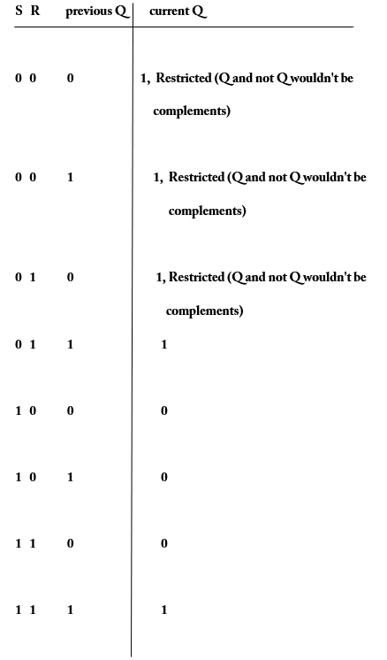
My suggestion would be:

enter image description here

Would that idea be right?

in the digital electronics means: S=1 => Q=1 and R=1 => Q=0

Edit: My question is different from the possible duplicate because I should work here with the previous Q (previous stored data).

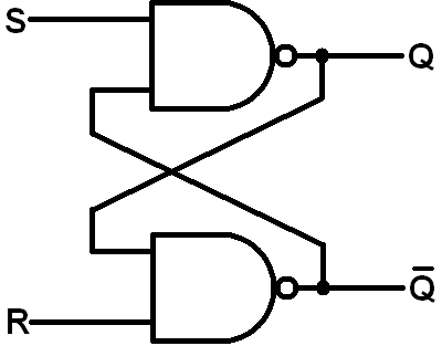
My task is to fill in this table the output Q by analysing following circuit

enter image description here

My suggestion would be:

enter image description here

Would that idea be right?

in the digital electronics means: S=1 => Q=1 and R=1 => Q=0

My task is to fill in this table the output Q by analysing following circuit

enter image description here

My suggestion would be:

enter image description here

Would that idea be right?

in the digital electronics means: S=1 => Q=1 and R=1 => Q=0

Edit: My question is different from the possible duplicate because I should work here with the previous Q (previous stored data).
deleted 4 characters in body
Source Link

Making Finding out the values in a statetruth table for a SR  - LatchLatch

My task is to create a statefill in this table for a SR-Latch which is build with NAND-Gates.the output Q by analysing following circuit

enter image description here

My suggestion would be:

enter image description here

Would that idea be right?

in the digital electronics means: S=1 => Q=1 and R=1 => Q=0

Making a state table for a SR  - Latch

My task is to create a state table for a SR-Latch which is build with NAND-Gates.enter image description here

My suggestion would be:

enter image description here

Would that idea be right?

in the digital electronics means: S=1 => Q=1 and R=1 => Q=0

Finding out the values in a truth table for a SR-Latch

My task is to fill in this table the output Q by analysing following circuit

enter image description here

My suggestion would be:

enter image description here

Would that idea be right?

in the digital electronics means: S=1 => Q=1 and R=1 => Q=0

added 63 characters in body
Source Link

My task is to create a state table for a SR-Latch which is build with NAND-Gates.enter image description here

My suggestion would be:

enter image description here

Would that idea be right?

in the digital electronics means: S=1 => Q=1 and R=1 => Q=0

My task is to create a state table for a SR-Latch which is build with NAND-Gates.enter image description here

My suggestion would be:

enter image description here

Would that idea be right?

My task is to create a state table for a SR-Latch which is build with NAND-Gates.enter image description here

My suggestion would be:

enter image description here

Would that idea be right?

in the digital electronics means: S=1 => Q=1 and R=1 => Q=0

edited tags
Link
Loading
added 85 characters in body
Source Link
Loading
edited title
Source Link
Loading
Source Link
Loading