added 200 characters in body
Source Link
sarthak
  • 3.8k
  • 5
  • 20
  • 31

Brief Background
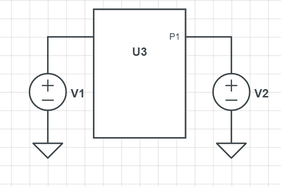
Suppose you have a linear network which has two input ports with input voltages \$V_1\$ and \$V_2\$ as shown in figure below:

enter image description here

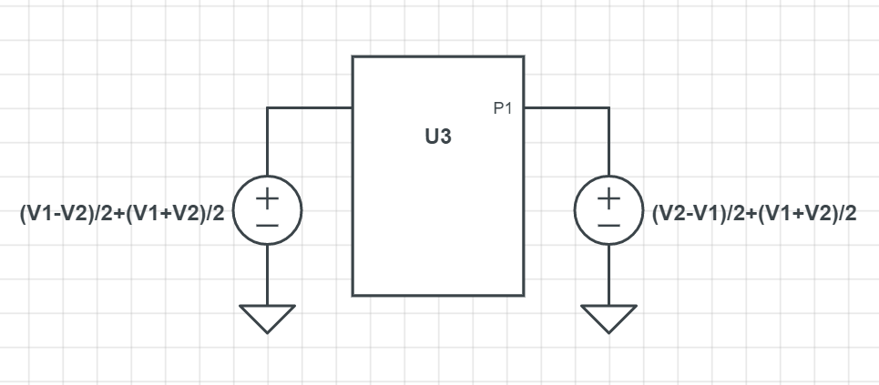
Then, since \$V_1 = \frac{V_1-V_2}{2}+\frac{V_1+V_2}{2}\$ and \$V_2=\frac{V_2-V_1}{2}+\frac{V_1+V_2}{2}\$. Thus we have:

enter image description here

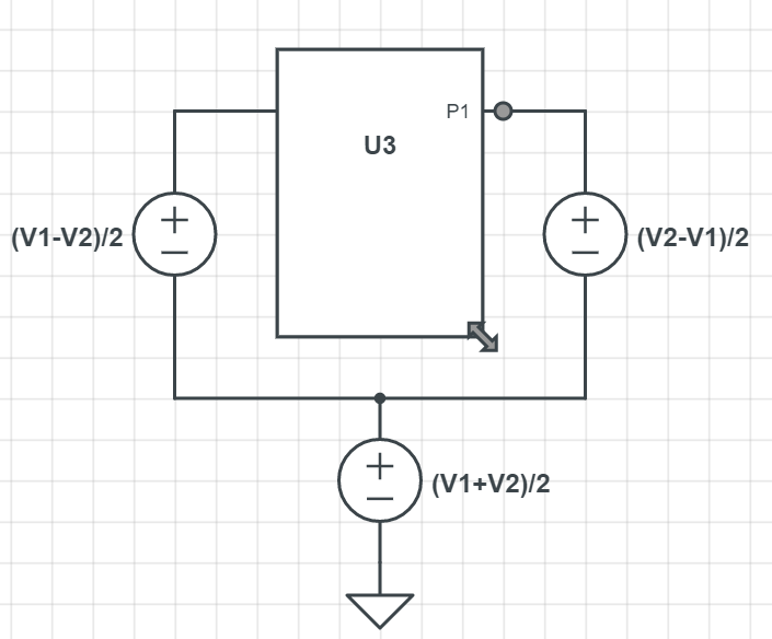
Then you can transform the circuit as shown below:

enter image description here

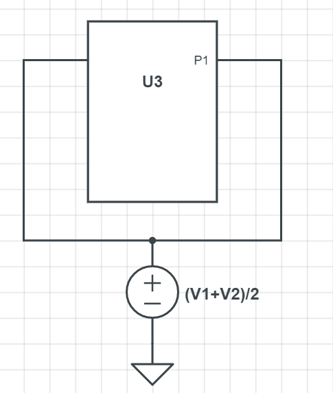
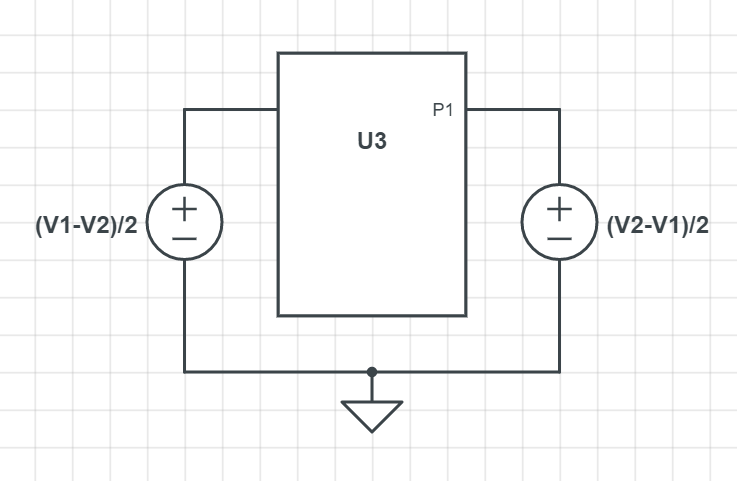
Here the common mode voltage is: \$V_{cm} = \frac{V_1+V_2}{2}\$ and the differential voltage is: \$\frac{V_{diff}}{2} = \frac{V_1-V_2}{2}\$. Since the circuit is linear, superposition is valid. So we can say that the total response will be sum of these two.

enter image description here

enter image description here

The first one is the the common-mode circuit and the second one is the differential circuit. Here you can use all the tricks for the differential half and the common-mode half which you may know.
Your Example
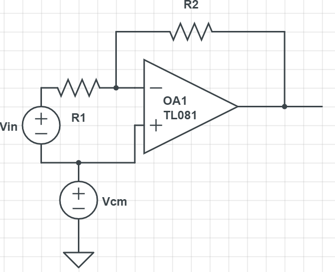
The complete circuit for the example you have provided is just a differential part wherewill be:

enter image description here

Here the two inputs are: \$V_1=V_{cm}+V_{in}\$ and \$V_2 = V_{cm}\$. The common-mode is grounded because it
If you use superposition here with \$V_{cm}=0\$, you get the circuit which you have shown in your question. This is athe differential halfpart of the circuit. So
If you instead make \$V_{in}=0\$, if you were to drawget the common-mode you would do like thiscircuit: enter image description here
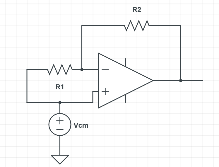
I leave it to you now to analyze it.
Brief Background
Suppose you have a linear network which has two input ports with input voltages \$V_1\$ and \$V_2\$ as shown in figure below:

enter image description here

Then, since \$V_1 = \frac{V_1-V_2}{2}+\frac{V_1+V_2}{2}\$ and \$V_2=\frac{V_2-V_1}{2}+\frac{V_1+V_2}{2}\$. Thus we have:

enter image description here

Then you can transform the circuit as shown below:

enter image description here

Here the common mode voltage is: \$V_{cm} = \frac{V_1+V_2}{2}\$ and the differential voltage is: \$\frac{V_{diff}}{2} = \frac{V_1-V_2}{2}\$. Since the circuit is linear, superposition is valid. So we can say that the total response will be sum of these two.

enter image description here

enter image description here

The first one is the the common-mode circuit and the second one is the differential circuit. Here you can use all the tricks for the differential half and the common-mode half which you may know.
Your Example
The circuit you have provided is just a differential part where the inputs are\$V_1=V_{cm}+V_{in}\$ and \$V_2 = V_{cm}\$. The common-mode is grounded because it is a differential half. So, if you were to draw the common-mode you would do like this: enter image description here

I leave it to you now to analyze it.
Brief Background
Suppose you have a linear network which has two input ports with input voltages \$V_1\$ and \$V_2\$ as shown in figure below:

enter image description here

Then, since \$V_1 = \frac{V_1-V_2}{2}+\frac{V_1+V_2}{2}\$ and \$V_2=\frac{V_2-V_1}{2}+\frac{V_1+V_2}{2}\$. Thus we have:

enter image description here

Then you can transform the circuit as shown below:

enter image description here

Here the common mode voltage is: \$V_{cm} = \frac{V_1+V_2}{2}\$ and the differential voltage is: \$\frac{V_{diff}}{2} = \frac{V_1-V_2}{2}\$. Since the circuit is linear, superposition is valid. So we can say that the total response will be sum of these two.

enter image description here

enter image description here

The first one is the the common-mode circuit and the second one is the differential circuit. Here you can use all the tricks for the differential half and the common-mode half which you may know.
Your Example
The complete circuit for the example you provided will be:

enter image description here

Here the two inputs are: \$V_1=V_{cm}+V_{in}\$ and \$V_2 = V_{cm}\$.
If you use superposition here with \$V_{cm}=0\$, you get the circuit which you have shown in your question. This is the differential part of the circuit.
If you instead make \$V_{in}=0\$, you get the common-mode circuit: enter image description here

I leave it to you now to analyze it.
Source Link
sarthak
  • 3.8k
  • 5
  • 20
  • 31

Brief Background
Suppose you have a linear network which has two input ports with input voltages \$V_1\$ and \$V_2\$ as shown in figure below:

enter image description here

Then, since \$V_1 = \frac{V_1-V_2}{2}+\frac{V_1+V_2}{2}\$ and \$V_2=\frac{V_2-V_1}{2}+\frac{V_1+V_2}{2}\$. Thus we have:

enter image description here

Then you can transform the circuit as shown below:

enter image description here

Here the common mode voltage is: \$V_{cm} = \frac{V_1+V_2}{2}\$ and the differential voltage is: \$\frac{V_{diff}}{2} = \frac{V_1-V_2}{2}\$. Since the circuit is linear, superposition is valid. So we can say that the total response will be sum of these two.

enter image description here

enter image description here

The first one is the the common-mode circuit and the second one is the differential circuit. Here you can use all the tricks for the differential half and the common-mode half which you may know.
Your Example
The circuit you have provided is just a differential part where the inputs are\$V_1=V_{cm}+V_{in}\$ and \$V_2 = V_{cm}\$. The common-mode is grounded because it is a differential half. So, if you were to draw the common-mode you would do like this: enter image description here

I leave it to you now to analyze it.