Brief Background
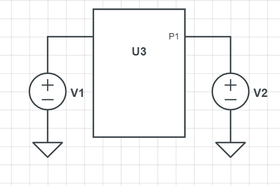
Suppose you have a linear network which has two input ports with input voltages \$V_1\$ and \$V_2\$ as shown in figure below:
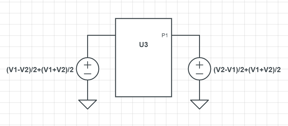
Then, since \$V_1 = \frac{V_1-V_2}{2}+\frac{V_1+V_2}{2}\$ and \$V_2=\frac{V_2-V_1}{2}+\frac{V_1+V_2}{2}\$. Thus we have:
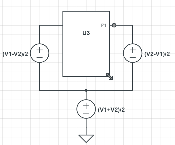
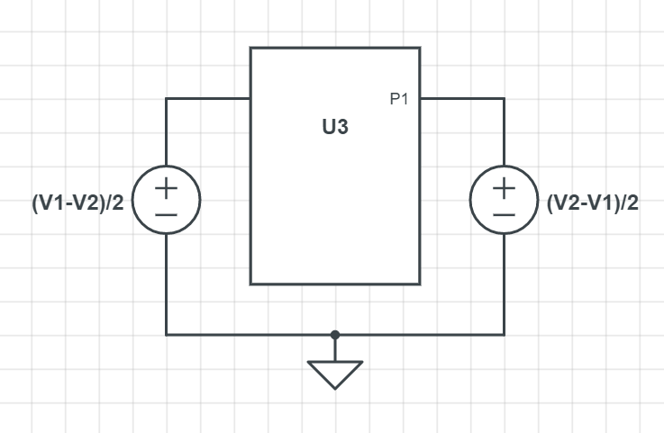
Then you can transform the circuit as shown below:
Here the common mode voltage is: \$V_{cm} = \frac{V_1+V_2}{2}\$ and the differential voltage is: \$\frac{V_{diff}}{2} = \frac{V_1-V_2}{2}\$. Since the circuit is linear, superposition is valid. So we can say that the total response will be sum of these two.
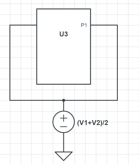
The first one is the the common-mode circuit and the second one is the differential circuit. Here you can use all the tricks for the differential half and the common-mode half which you may know.
Your Example
The circuit you have provided is just a differential part where the inputs are\$V_1=V_{cm}+V_{in}\$ and \$V_2 = V_{cm}\$. The common-mode is grounded because it is a differential half. So, if you were to draw the common-mode you would do like this:
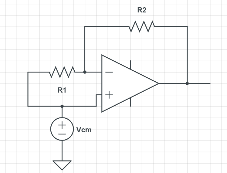
I leave it to you now to analyze it.

