Tweeted twitter.com/StackElectronix/status/1615000944780972033
deleted 2 characters in body
Source Link
ssa2
  • 93
  • 1
  • 7

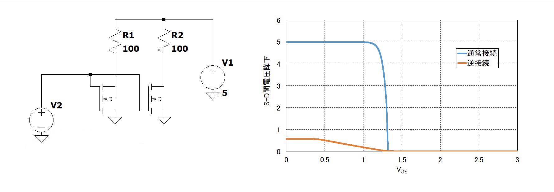
The circuit shown below is implemented using two AO3400 N-MOSFETs.
AO4300 datasheet here.

The right-hand MOSFET is connected with normal polarity (Vds is positive),
while the left-hand MOSFET is connected with reverse polarity (Vds is negative).

The graph at below right shows the relationship between Vgs and Vds simulated by LTSpice.
The blue curve is for the normally connected FET, and
the orange curve is for the reverse connected FET.

At low Vgs (<< Vgs(th)), the reverse connected MOSFET is conducting due to current in the body diode, resulting in a Vds value of about 0.6 V. As Vgs increases to above 0.4V , Vds starts towards GND level.

Why does the reverse connected MOSFET starts to turn on from about Vgs = 0.4 V when this MOSFET has about 1.1 V threshold?

enter image description hereenter image description here

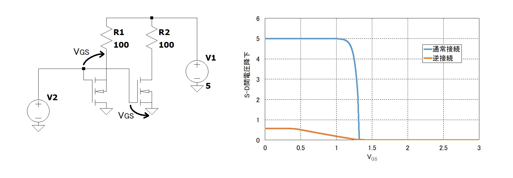
The circuit shown below is implemented using two AO3400 N-MOSFETs.
AO4300 datasheet here.

The right-hand MOSFET is connected with normal polarity (Vds is positive),
while the left-hand MOSFET is connected with reverse polarity (Vds is negative).

The graph at below right shows the relationship between Vgs and Vds simulated by LTSpice.
The blue curve is for the normally connected FET, and
the orange curve is for the reverse connected FET.

At low Vgs (<< Vgs(th)), the reverse connected MOSFET is conducting due to current in the body diode, resulting in a Vds value of about 0.6 V. As Vgs increases to above 0.4V , Vds starts towards GND level.

Why does the reverse connected MOSFET starts to turn on from about Vgs = 0.4 V when this MOSFET has about 1.1 V threshold?
enter image description here

deleted 2 characters in body; added 2 characters in body
Source Link
ssa2
  • 93
  • 1
  • 7

The circuit shown below is implemented using two AO3400 N-MOSFETs.
AO4300 datasheet here.

The right-hand MOSFET is connected with normal polarity (Vds is positive),
while the left-hand MOSFET is connected with reverse polarity (Vds is negative).

The graph at below right shows the relationship between Vgs and Vds simulated by LTSpice.
The blue curve is for the normally connected FET, and
the orange curve is for the reverse connected FET.

At low Vgs (<< Vgs(th)), the reverse connected MOSFET is conducting due to current in the body diode, resulting in a Vds value of about 0.6 V. As Vgs increases to above 0.4V , Vds starts towards GND level.

Why does the reverse connected MOSFET starts to turn on from about Vgs >= 0.4 V when this MOSFET has about 1.1 V threshold?

enter image description here

The circuit shown below is implemented using two AO3400 N-MOSFETs.
AO4300 datasheet here.

The right-hand MOSFET is connected with normal polarity (Vds is positive),
while the left-hand MOSFET is connected with reverse polarity (Vds is negative).

The graph at below right shows the relationship between Vgs and Vds simulated by LTSpice.
The blue curve is for the normally connected FET, and
the orange curve is for the reverse connected FET.

At low Vgs (<< Vgs(th)), the reverse connected MOSFET is conducting due to current in the body diode, resulting in a Vds value of about 0.6 V. As Vgs increases to above 0.4V , Vds starts towards GND level.

Why does the reverse connected MOSFET starts to turn on from about Vgs > 0.4 V when this MOSFET has about 1.1 V threshold?

enter image description here

The circuit shown below is implemented using two AO3400 N-MOSFETs.
AO4300 datasheet here.

The right-hand MOSFET is connected with normal polarity (Vds is positive),
while the left-hand MOSFET is connected with reverse polarity (Vds is negative).

The graph at below right shows the relationship between Vgs and Vds simulated by LTSpice.
The blue curve is for the normally connected FET, and
the orange curve is for the reverse connected FET.

At low Vgs (<< Vgs(th)), the reverse connected MOSFET is conducting due to current in the body diode, resulting in a Vds value of about 0.6 V. As Vgs increases to above 0.4V , Vds starts towards GND level.

Why does the reverse connected MOSFET starts to turn on from about Vgs = 0.4 V when this MOSFET has about 1.1 V threshold?

enter image description here

deleted 71 characters in body
Source Link
ssa2
  • 93
  • 1
  • 7

The circuit shown below is implemented using two AO3400 N-MOSFETs.
AO4300 datasheet here.

The right-hand MOSFET is connected with normal polarity (Vds is positive),
while the left-hand MOSFET is connected with reverse polarity (Vds is negative).

The graph at below right shows the relationship between Vgs and Vds simulated by LTSpice.
The blue curve is for the normally connected FET, and
the orange curve is for the reverse connected FET.

At low Vgs (<< Vgs(th)), the reverse connected MOSFET is conducting due to current in the body diode, resulting in a Vds value of about 0.6 V. As Vgs increases to above 0.5V4V , Vds starts towards GND level, until Vds of both FETs reaches != 0V when Vgs is about 1.4V. at 0.5V.

Why does the reverse connected MOSFET starts to turn on from about Vgs >=> 0.4 V when this MOSFET has about 1.1 V threshold?

enter image description here

The circuit shown below is implemented using two AO3400 N-MOSFETs.
AO4300 datasheet here.

The right-hand MOSFET is connected with normal polarity (Vds is positive),
while the left-hand MOSFET is connected with reverse polarity (Vds is negative).

The graph at below right shows the relationship between Vgs and Vds simulated by LTSpice.
The blue curve is for the normally connected FET, and
the orange curve is for the reverse connected FET.

At low Vgs (<< Vgs(th)), the reverse connected MOSFET is conducting due to current in the body diode, resulting in a Vds value of about 0.6 V. As Vgs increases to above 0.5V , Vds starts towards GND level, until Vds of both FETs reaches != 0V when Vgs is about 1.4V. at 0.5V.

Why does the reverse connected MOSFET starts to turn on from about Vgs >= 0.4 V when this MOSFET has about 1.1 V threshold?

enter image description here

The circuit shown below is implemented using two AO3400 N-MOSFETs.
AO4300 datasheet here.

The right-hand MOSFET is connected with normal polarity (Vds is positive),
while the left-hand MOSFET is connected with reverse polarity (Vds is negative).

The graph at below right shows the relationship between Vgs and Vds simulated by LTSpice.
The blue curve is for the normally connected FET, and
the orange curve is for the reverse connected FET.

At low Vgs (<< Vgs(th)), the reverse connected MOSFET is conducting due to current in the body diode, resulting in a Vds value of about 0.6 V. As Vgs increases to above 0.4V , Vds starts towards GND level.

Why does the reverse connected MOSFET starts to turn on from about Vgs > 0.4 V when this MOSFET has about 1.1 V threshold?

enter image description here

deleted 7 characters in body
Source Link
ssa2
  • 93
  • 1
  • 7
Loading
edited body
Source Link
ssa2
  • 93
  • 1
  • 7
Loading
added 9 characters in body
Source Link
Russell McMahon
  • 152.1k
  • 18
  • 218
  • 403
Loading
added 9 characters in body
Source Link
Russell McMahon
  • 152.1k
  • 18
  • 218
  • 403
Loading
added 5 characters in body
Source Link
ssa2
  • 93
  • 1
  • 7
Loading
Source Link
ssa2
  • 93
  • 1
  • 7
Loading