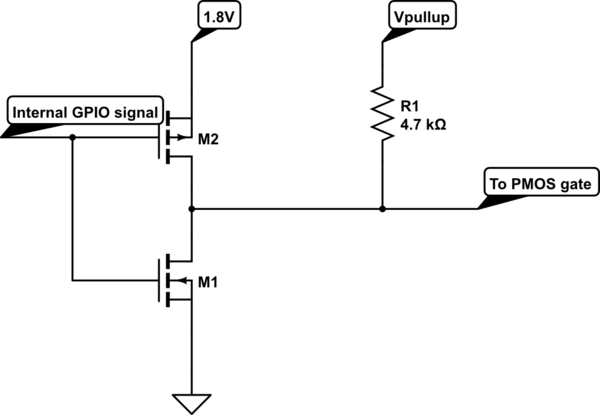
The output is very likely a push pull stage which has a (relatively) low output resistance.
What you effectively have is this (assuming you are using a CMOS device)

simulate this circuit – Schematic created using CircuitLab
The output when high will have M2 on and M1 off.
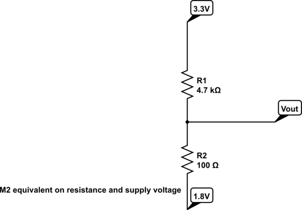
The output of this stage when high will have a typical resistance to 1.8V of perhaps a few tens (sometimes higher) of ohms; the voltage divider formed of M2 and the pullup resistor will maintain the output voltage at close to the GPIO drive voltage of 1.8V
You could use an open drain output but ensure it is safe to use with a 3.3V pullup (that will be in the datasheet).
The effective circuit in the high output state is this:

From the voltage divider principle, the voltage at Vout will be 1.83125V (assuming the on resistance of M2 is 100 ohms).
You should not normally pull a push pull / totem pole output beyond its supply voltages whether that be positive or negative.
