Notice removed Draw attention by CommunityBot
Bounty Ended with no winning answer by CommunityBot
added 95 characters in body
Source Link

Second this week... But was it easy I wouldn't be here...

A problem asked me to identify the diagrams from this picture:
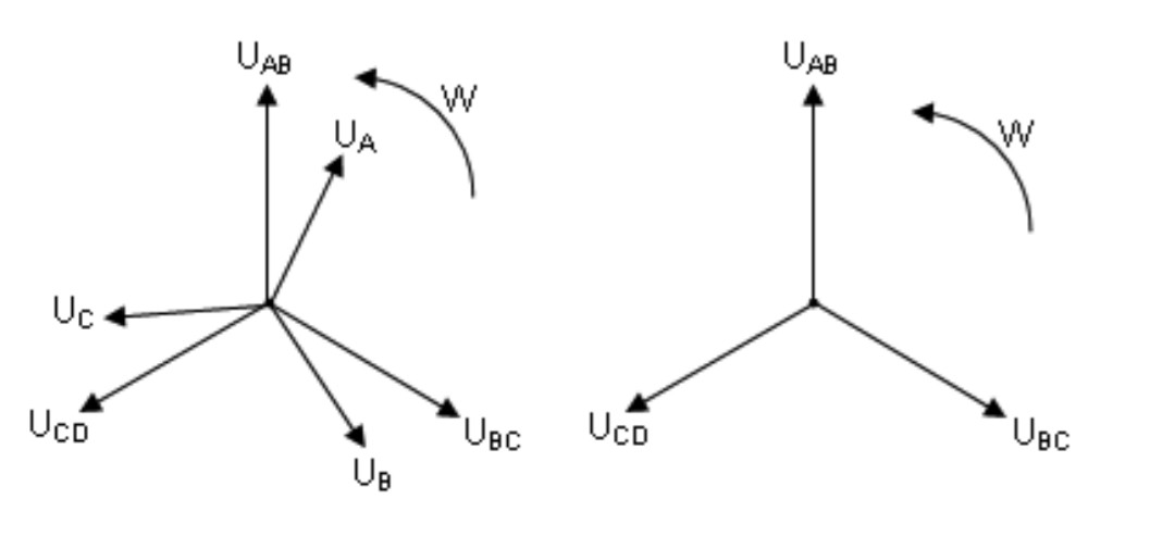
Diagrams

The following are the correct answers, acording to the test developers.

a. The first diagram may represent the voltage over the load of a 4-wire Unbalanced Star.

b. The first diagram may represent the voltage over the load of a 3-wire Balanced Star.

c. The second diagram may represent the voltage over the load of a 3-wire Balanced Star.

d. The second diagram may represent the voltage over the load of an Unbalanced Delta

Again: all the above assertions are to be taken as true


I need help understanding these truths/assertions.


  • As far as I know, the line voltage is 30 degrees ahead of the phase voltage on a star connection (a neutral wire enforces this in case one of the impedances is not equal)

This knowledge matches the a. and b., but doesn't seem to my eyes to make sense for c.. How is the assertion c. possible ?

  • As far as I know, the line and phase voltages on deltas are equal, with No angle between them. But that wouldn't match assertion d. How is such assertion possible ?

Maybe the trick is in the distinction between load and source...

Who has the patience for this ? If I think any longer I lose my sanity

This is an adaptation of the actual question. The original is longer and not in english.not in english. I may share if requested.Here, question number 29: https://arquivo.pciconcursos.com.br/provas/21572117/1fc8bd07ea0/tecnico_eletrotecnica.pdf

*I believe the D letter in the diagram is a typo

Second this week... But was it easy I wouldn't be here...

A problem asked me to identify the diagrams from this picture:

Diagrams

The following are the correct answers, acording to the test developers.

a. The first diagram may represent the voltage over the load of a 4-wire Unbalanced Star.

b. The first diagram may represent the voltage over the load of a 3-wire Balanced Star.

c. The second diagram may represent the voltage over the load of a 3-wire Balanced Star.

d. The second diagram may represent the voltage over the load of an Unbalanced Delta

Again: all the above assertions are to be taken as true


I need help understanding these truths/assertions.


  • As far as I know, the line voltage is 30 degrees ahead of the phase voltage on a star connection (a neutral wire enforces this in case one of the impedances is not equal)

This knowledge matches the a. and b., but doesn't seem to my eyes to make sense for c.. How is the assertion c. possible ?

  • As far as I know, the line and phase voltages on deltas are equal, with No angle between them. But that wouldn't match assertion d. How is such assertion possible ?

Maybe the trick is in the distinction between load and source...

Who has the patience for this ? If I think any longer I lose my sanity

This is an adaptation of the actual question. The original is longer and not in english. I may share if requested.

*I believe the D letter in the diagram is a typo

Second this week... But was it easy I wouldn't be here...

A problem asked me to identify the diagrams from this picture:

Diagrams

The following are the correct answers, acording to the test developers.

a. The first diagram may represent the voltage over the load of a 4-wire Unbalanced Star.

b. The first diagram may represent the voltage over the load of a 3-wire Balanced Star.

c. The second diagram may represent the voltage over the load of a 3-wire Balanced Star.

d. The second diagram may represent the voltage over the load of an Unbalanced Delta

Again: all the above assertions are to be taken as true


I need help understanding these truths/assertions.


  • As far as I know, the line voltage is 30 degrees ahead of the phase voltage on a star connection (a neutral wire enforces this in case one of the impedances is not equal)

This knowledge matches the a. and b., but doesn't seem to my eyes to make sense for c.. How is the assertion c. possible ?

  • As far as I know, the line and phase voltages on deltas are equal, with No angle between them. But that wouldn't match assertion d. How is such assertion possible ?

Maybe the trick is in the distinction between load and source...

Who has the patience for this ? If I think any longer I lose my sanity

This is an adaptation of the actual question. The original is longer and not in english. Here, question number 29: https://arquivo.pciconcursos.com.br/provas/21572117/1fc8bd07ea0/tecnico_eletrotecnica.pdf

*I believe the D letter in the diagram is a typo

Notice added Draw attention by Lucas BS
Bounty Started worth 50 reputation by Lucas BS
Spelling, organization
Source Link

Second this week... But was it easy I wouldn't be here...

A problem asked me to identify the diagrams from this picture:

Diagrams

The following are the correct answers, acording to the test developers.

a. The first diagram may represent the voltage over the load of a 4-wire Unbalanced Star.

b. The first diagram may represent the voltage over the load of a 3-wire Balanced Star.

c. The second diagram may represent the voltage over the load of a 3-wire Balanced Star.

d. The second diagram may represent the voltage over the load of an Unbalanced Delta

Again: all the above assertions are to be taken as true


I need help understanding these truths/assertions.


  • As far as I know, the line voltage is 30 degrees ahead of the phase voltage on a star connection (a neutral wire enforces this in case one of the inpedancesimpedances is not equal)

This knowledge matches the a. and b., but doesn't seem to my eyes to make sense for c.. How is the assertion c. possible ?

  • As far as I know, the line and phase voltages on deltas are equal, with No angle between them. But that wouldn't match assertion d. How is such assertion possible ?

Maybe the trick is in the distinction between load and source...

Who has the patience for this ? If I think any longer I lose my sanity

This is an adaptation of the actual question. The original is longer and not in english. I may share if requested.

*I believe the D letter in the diagram is a typo

Second this week... But was it easy I wouldn't be here...

A problem asked me to identify the diagrams from this picture:

Diagrams

The following are the correct answers, acording to the test developers.

a. The first diagram may represent the voltage over the load of a 4-wire Unbalanced Star.

b. The first diagram may represent the voltage over the load of a 3-wire Balanced Star.

c. The second diagram may represent the voltage over the load of a 3-wire Balanced Star.

d. The second diagram may represent the voltage over the load of an Unbalanced Delta

Again: all the above assertions are to be taken as true


I need help understanding these truths/assertions.


  • As far as I know, the line voltage is 30 degrees ahead of the phase voltage on a star connection (a neutral wire enforces this in case one of the inpedances is not equal)

This knowledge matches the a. and b., but doesn't seem to my eyes to make sense for c.. How is the assertion c. possible ?

  • As far as I know, the line and phase voltages on deltas are equal, with No angle between them. But that wouldn't match assertion d. How is such assertion possible ?

Maybe the trick is in the distinction between load and source...

Who has the patience for this ? If I think any longer I lose my sanity

This is an adaptation of the actual question. The original is longer and not in english. I may share if requested.

*I believe the D letter in the diagram is a typo

Second this week... But was it easy I wouldn't be here...

A problem asked me to identify the diagrams from this picture:

Diagrams

The following are the correct answers, acording to the test developers.

a. The first diagram may represent the voltage over the load of a 4-wire Unbalanced Star.

b. The first diagram may represent the voltage over the load of a 3-wire Balanced Star.

c. The second diagram may represent the voltage over the load of a 3-wire Balanced Star.

d. The second diagram may represent the voltage over the load of an Unbalanced Delta

Again: all the above assertions are to be taken as true


I need help understanding these truths/assertions.


  • As far as I know, the line voltage is 30 degrees ahead of the phase voltage on a star connection (a neutral wire enforces this in case one of the impedances is not equal)

This knowledge matches the a. and b., but doesn't seem to my eyes to make sense for c.. How is the assertion c. possible ?

  • As far as I know, the line and phase voltages on deltas are equal, with No angle between them. But that wouldn't match assertion d. How is such assertion possible ?

Maybe the trick is in the distinction between load and source...

Who has the patience for this ? If I think any longer I lose my sanity

This is an adaptation of the actual question. The original is longer and not in english. I may share if requested.

*I believe the D letter in the diagram is a typo

added 4 characters in body
Source Link

Second this week... But was it easy I wouldn't be here...

A problem asked me to identify the diagrams from this picture:A problem asked me to identify the diagrams from this picture:

Diagrams

The following are the correct answers, acording to the test developers. Again, all these assertions are to be taken as true:

a. The first diagram MAYmay represent the voltage over the load of a 4-wire Unbalanced Star.

b. The first diagram MAYmay represent the voltage over the load of a 3-wire Balanced Star.

c. The second diagram MAYmay represent the voltage over the load of a 3-wire Balanced Star.

d. The second diagram MAYmay represent the voltage over the load of an Unbalanced Delta

Again: all the above assertions are to be taken as true


I need help understanding these truths/assertions.


  • As far as I know, the line voltage is 30 degrees ahead of the phase voltage on a star connection (a neutral wire enforces this in case one of the phasesinpedances is not equal)

This knowledge matches the a. and b., but doesn't seem to my eyes to make sense for c.. How is the assertion c. possible ?

  • As far as I know, the line and phase voltages on deltas are equal, with No angle between them. But that wouldn't match assertion d. How is such assertion possible ?

Maybe the trick is in the distinction between load and source...

Who has the patience for this ? If I think any longer I lose my sanity

This is an adaptation of the actual question. The original is longer and not in english. I may share if requested.

*I believe the D letter in the diagram is a typo

Second this week... But was it easy I wouldn't be here...

A problem asked me to identify the diagrams from this picture:

Diagrams

The following are the correct answers, acording to the test developers. Again, all these assertions are to be taken as true:

a. The first diagram MAY represent the voltage over the load of a 4-wire Unbalanced Star.

b. The first diagram MAY represent the voltage over the load of a 3-wire Balanced Star.

c. The second diagram MAY represent the voltage over the load of a 3-wire Balanced Star.

d. The second diagram MAY represent the voltage over the load of an Unbalanced Delta


I need help understanding these truths/assertions.


  • As far as I know, the line voltage is 30 degrees ahead of the phase voltage on a star connection (a neutral wire enforces this in case one of the phases is not equal)

This knowledge matches the a. and b., but doesn't seem to my eyes to make sense for c.. How is the assertion c. possible ?

  • As far as I know, the line and phase voltages on deltas are equal, with No angle between them. But that wouldn't match assertion d. How is such assertion possible ?

Maybe the trick is in the distinction between load and source...

Who has the patience for this ? If I think any longer I lose my sanity

This is an adaptation of the actual question. The original is longer and not in english. I may share if requested.

*I believe the D letter in the diagram is a typo

Second this week... But was it easy I wouldn't be here...

A problem asked me to identify the diagrams from this picture:

Diagrams

The following are the correct answers, acording to the test developers.

a. The first diagram may represent the voltage over the load of a 4-wire Unbalanced Star.

b. The first diagram may represent the voltage over the load of a 3-wire Balanced Star.

c. The second diagram may represent the voltage over the load of a 3-wire Balanced Star.

d. The second diagram may represent the voltage over the load of an Unbalanced Delta

Again: all the above assertions are to be taken as true


I need help understanding these truths/assertions.


  • As far as I know, the line voltage is 30 degrees ahead of the phase voltage on a star connection (a neutral wire enforces this in case one of the inpedances is not equal)

This knowledge matches the a. and b., but doesn't seem to my eyes to make sense for c.. How is the assertion c. possible ?

  • As far as I know, the line and phase voltages on deltas are equal, with No angle between them. But that wouldn't match assertion d. How is such assertion possible ?

Maybe the trick is in the distinction between load and source...

Who has the patience for this ? If I think any longer I lose my sanity

This is an adaptation of the actual question. The original is longer and not in english. I may share if requested.

*I believe the D letter in the diagram is a typo

added 43 characters in body
Source Link
Loading
added 199 characters in body
Source Link
Loading
added 6 characters in body
Source Link
Loading
Source Link
Loading