Bumped by Community user
added 10 characters in body; edited title
Source Link
ocrdu
  • 9.3k
  • 23
  • 32
  • 42

BTA12 Triactriac driver circuit

schematic

I'm using the circuit in the picture as a replacement for a mechanical relay running a 40 wattW, 220 voltV water pump.

The problem is that although the circuit seems to be correct, but it doesn't work, and I'm getting a weird result on the multimeter.

When monitoring the AC output of the circuit with a multimeter, it shows 220 voltsV when the logic input of the moc3042m is low. Also, this voltage doesn't turn on the pump. When changing the logic input to high (5 V), the output doesn't change.

  • The actual pump is connected to the J4 terminal.
  • The Pump label in the picture is for the logic input.

If you see any problem in the schematic, please explain it.

BTA12 Triac driver circuit

schematic

I'm using circuit in the picture as a replacement for a mechanical relay running a 40 watt 220 volt water pump.

The problem is the circuit seems to be correct, but it doesn't work and I'm getting a weird result on the multimeter.

When monitoring the AC output of the circuit with a multimeter, it shows 220 volts when the logic input of the moc3042m is low. Also, this voltage doesn't turn on the pump. When changing logic input to high (5 V), the output doesn't change.

  • The actual pump is connected to the J4 terminal.
  • The Pump label in the picture is for the logic input.

If you see any problem in the schematic, please explain it.
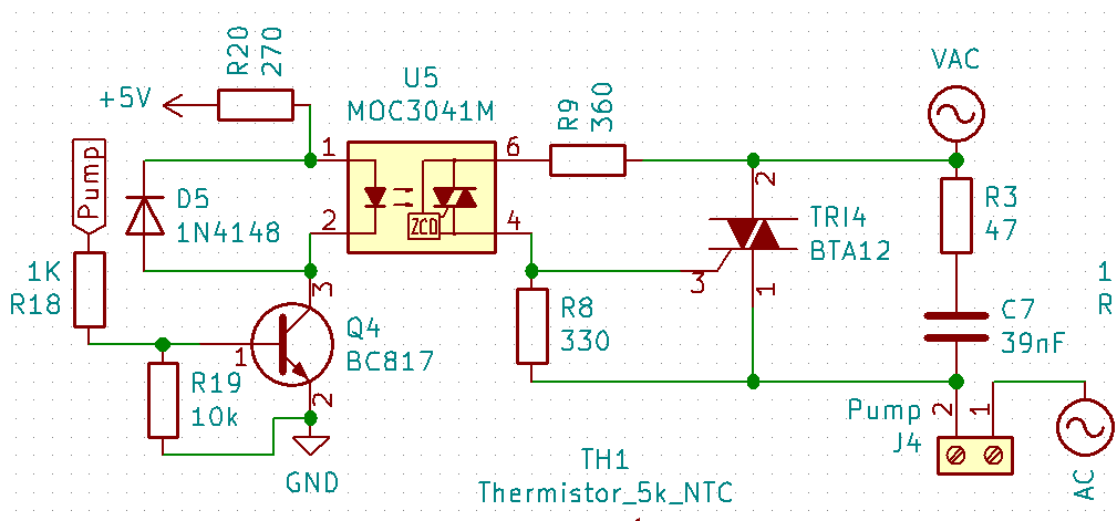
BTA12 triac driver circuit

schematic

I'm using the circuit in the picture as a replacement for a mechanical relay running a 40 W, 220 V water pump.

The problem is that although the circuit seems to be correct, it doesn't work, and I'm getting a weird result on the multimeter.

When monitoring the AC output of the circuit with a multimeter, it shows 220 V when the logic input of the moc3042m is low. Also, this voltage doesn't turn on the pump. When changing the logic input to high (5 V), the output doesn't change.

  • The actual pump is connected to the J4 terminal.
  • The Pump label in the picture is for the logic input.

If you see any problem in the schematic, please explain it.

Bumped by Community user
Split text (mostly where intended by OP, but where only 1 x Enter had been used) to prevent "wall of text". Some grammar changes to improve readability.
Source Link
SamGibson
  • 18.3k
  • 5
  • 41
  • 63

enter image description hereschematic

I'm using circuit in the picture as a replacement for a mechanical relay for running a 40 watt 220v220 volt water pump. the

The problem is the circuit seems to be correct, but it doesn't work and I'm getting wireda weird result on the multimeter. when

When monitoring acthe AC output of the circuit with a multimeter, it shows 220 voltagevolts when the logic input of the moc3042m is low and also. Also, this voltage doesn't turn pump on and whenthe pump. When changing logic input to high (5v5 V), the out putoutput doesn't change.

  • The actual pump is connected to J4the J4 terminal and Pump.
  • The Pump label in the picture is for the logic input.

If you see any problem in circuitthe schematic, please mentionexplain it.

enter image description here

I'm using circuit in the picture as a replacement for mechanical relay for running 40 watt 220v water pump. the problem is the circuit seems to be correct but it doesn't work and getting wired result on multimeter. when monitoring ac output of the circuit with multimeter it shows 220 voltage when the logic input of the moc3042m is low and also this voltage doesn't turn pump on and when changing logic input to high (5v) the out put doesn't change.

  • pump is connected to J4 terminal and Pump label in picture is for logic input.

If you see any problem in circuit please mention it.

schematic

I'm using circuit in the picture as a replacement for a mechanical relay running a 40 watt 220 volt water pump.

The problem is the circuit seems to be correct, but it doesn't work and I'm getting a weird result on the multimeter.

When monitoring the AC output of the circuit with a multimeter, it shows 220 volts when the logic input of the moc3042m is low. Also, this voltage doesn't turn on the pump. When changing logic input to high (5 V), the output doesn't change.

  • The actual pump is connected to the J4 terminal.
  • The Pump label in the picture is for the logic input.

If you see any problem in the schematic, please explain it.

Source Link
A.M.S
  • 19
  • 5

BTA12 Triac driver circuit

enter image description here

I'm using circuit in the picture as a replacement for mechanical relay for running 40 watt 220v water pump. the problem is the circuit seems to be correct but it doesn't work and getting wired result on multimeter. when monitoring ac output of the circuit with multimeter it shows 220 voltage when the logic input of the moc3042m is low and also this voltage doesn't turn pump on and when changing logic input to high (5v) the out put doesn't change.

  • pump is connected to J4 terminal and Pump label in picture is for logic input.

If you see any problem in circuit please mention it.