added an extra option 5, posted information about my actual schematic
Source Link
Bruce
  • 1.1k
  • 7
  • 18

I designed a PCB to drive mosfets with a ESP32 micro-controller. The ESP32 will be connected to the PCB with wires from a separate PCB. When there is no micro-controller connected to the input of the Mosfet PCB all Mosfets should be turned on. So I connected a pull-up resistor to their gate. The only onboard voltage is 12V so the pull-up is connected to the 12V as well. When nothing is connected the voltage at the input pins will be 12V because of the ESP32. this doesn't seem a safe scenario to me for connecting a micro-controller. I worked out a few possible solutions.

  1. Default scenario
  2. Using a voltage divider
  3. Using a 3V zener diode at the input
  4. Creating a separate 3V source with a zener diode, and use this source to connect the pull-up.
  5. (UPDATE) instead of option 4 use a voltage regulator to connect a pull-up to

For each scenario I've written my thoughts next to it. I'm not sure which one I should pick. What is the best practice in this scenario? Opto-couplers might be but they slow down my switching time to much.

Thanks in advance

enter image description here

Link to simulation in falstad


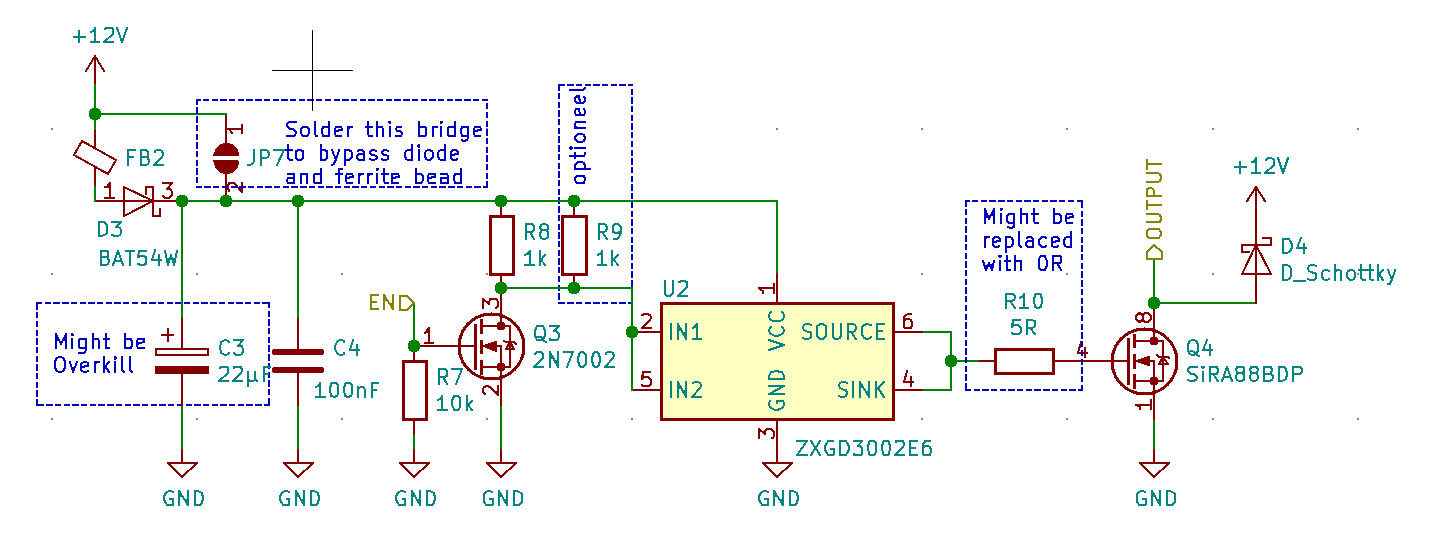
UPDATE This is my actual schematic I'm using at the moment. R7 Needs to be changed to a pull-up that's the one I was talking about.

A little bit more info on my circuit.

  • Q4 is the power-mosfet that will get a voltage of 0V or 12V at its gate. From Mosfet driver U2.
  • U2 is a mostfet driver with the internal schematic of a totem pole transistor configuration. To get around 12V at it's output we need 12V at it's input.
  • To to make a 12V to 0V input voltage at U2 controller by only a 0-3.3V control voltage I use Q3 a N-CH Mosfet with a pull-up resistor.

Actual schematic

The reason I'm using this mosfet driver and I'm not controlling it directly is because I need a very high switching speed. At the moment when I measured this I only have a 33ns delay between input and output. And I'm afraid that adding an extra transistor or mosfet will slow down the propagation time even more.

If a transistor is faster than a mosfet which I guess it is I would gladly change Q3 for a transistor. But then I'm in the same situation as before with the pull-up at the gate/base.

I designed a PCB to drive mosfets with a ESP32 micro-controller. The ESP32 will be connected to the PCB with wires from a separate PCB. When there is no micro-controller connected to the input of the Mosfet PCB all Mosfets should be turned on. So I connected a pull-up resistor to their gate. The only onboard voltage is 12V so the pull-up is connected to the 12V as well. When nothing is connected the voltage at the input pins will be 12V because of the ESP32. this doesn't seem a safe scenario to me for connecting a micro-controller. I worked out a few possible solutions.

  1. Default scenario
  2. Using a voltage divider
  3. Using a 3V zener diode at the input
  4. Creating a separate 3V source with a zener diode, and use this source to connect the pull-up.

For each scenario I've written my thoughts next to it. I'm not sure which one I should pick. What is the best practice in this scenario? Opto-couplers might be but they slow down my switching time to much.

Thanks in advance

enter image description here

Link to simulation in falstad

I designed a PCB to drive mosfets with a ESP32 micro-controller. The ESP32 will be connected to the PCB with wires from a separate PCB. When there is no micro-controller connected to the input of the Mosfet PCB all Mosfets should be turned on. So I connected a pull-up resistor to their gate. The only onboard voltage is 12V so the pull-up is connected to the 12V as well. When nothing is connected the voltage at the input pins will be 12V because of the ESP32. this doesn't seem a safe scenario to me for connecting a micro-controller. I worked out a few possible solutions.

  1. Default scenario
  2. Using a voltage divider
  3. Using a 3V zener diode at the input
  4. Creating a separate 3V source with a zener diode, and use this source to connect the pull-up.
  5. (UPDATE) instead of option 4 use a voltage regulator to connect a pull-up to

For each scenario I've written my thoughts next to it. I'm not sure which one I should pick. What is the best practice in this scenario? Opto-couplers might be but they slow down my switching time to much.

Thanks in advance

enter image description here

Link to simulation in falstad


UPDATE This is my actual schematic I'm using at the moment. R7 Needs to be changed to a pull-up that's the one I was talking about.

A little bit more info on my circuit.

  • Q4 is the power-mosfet that will get a voltage of 0V or 12V at its gate. From Mosfet driver U2.
  • U2 is a mostfet driver with the internal schematic of a totem pole transistor configuration. To get around 12V at it's output we need 12V at it's input.
  • To to make a 12V to 0V input voltage at U2 controller by only a 0-3.3V control voltage I use Q3 a N-CH Mosfet with a pull-up resistor.

Actual schematic

The reason I'm using this mosfet driver and I'm not controlling it directly is because I need a very high switching speed. At the moment when I measured this I only have a 33ns delay between input and output. And I'm afraid that adding an extra transistor or mosfet will slow down the propagation time even more.

If a transistor is faster than a mosfet which I guess it is I would gladly change Q3 for a transistor. But then I'm in the same situation as before with the pull-up at the gate/base.
Source Link
Bruce
  • 1.1k
  • 7
  • 18

Microcontroller driver the gate of a mosfet with a pull up resistor to 12V

I designed a PCB to drive mosfets with a ESP32 micro-controller. The ESP32 will be connected to the PCB with wires from a separate PCB. When there is no micro-controller connected to the input of the Mosfet PCB all Mosfets should be turned on. So I connected a pull-up resistor to their gate. The only onboard voltage is 12V so the pull-up is connected to the 12V as well. When nothing is connected the voltage at the input pins will be 12V because of the ESP32. this doesn't seem a safe scenario to me for connecting a micro-controller. I worked out a few possible solutions.

  1. Default scenario
  2. Using a voltage divider
  3. Using a 3V zener diode at the input
  4. Creating a separate 3V source with a zener diode, and use this source to connect the pull-up.

For each scenario I've written my thoughts next to it. I'm not sure which one I should pick. What is the best practice in this scenario? Opto-couplers might be but they slow down my switching time to much.

Thanks in advance

enter image description here

Link to simulation in falstad