added 1143 characters in body
Source Link
hacktastical
  • 58.4k
  • 2
  • 54
  • 166

Ugh. This again. tl, dr: The gated JK latch is a junk circuit and should not be used in a modern design. It's useless, except as a lesson of how not to design a latch.

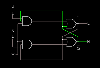
Let's start with the The Ben Eater drawing. It's wrong - the feedbacks are crossed.

enter image description here

Ben Eater's broken version in Falstad

As you can see, this doesn't do anything.

So let's fix the feedback connections...

enter image description here

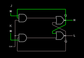
try it here with Falstad. It oscillates

... uh oh, there's a problem. We now have a working (sorta) gated JK latch, and we can see this behavior:

  • J, K = 0, 0: hold
  • J, K = 1, 0: Q = 1, Qbar = 0 at clock rise
  • J, K = 0, 1: Q = 0, Qbar = 1 at clock rise
  • J, K = 1, 1: very bad things when clock is high

The expected Q/Qbar toggle with J and K high doesn't happen. It oscillates!

Why? When both the J and K inputs are ‘1’ and clock is high, the two NORs and ANDs form a pair of inverters wired head-to-tail. With all the inputs high, you have a ring oscillator, a useful circuit by itself (it's used in PLLs for example), but not here. This oscillation is sometimes called "race-around", and was a (mis-)feature of early JK flop logic designs (yes, including Jack Kilby's).

Instead, we want the state to change only at clock rise. We have two ways to do that:

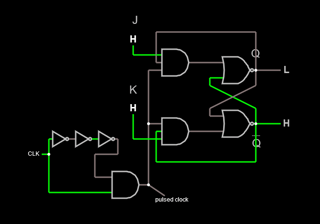
  • use a rising-edge detect on the clock that generates a pulse narrow enough to suppress the 'race around'
  • use two gated latch stages, each controlled by opposite clock phase

The first approach is a hack to save gates. While it worked with early logic that was slow, no one in their right mind would do a clocked JK flop that way today.

Nevertheless, in the interest of completeness, here's an example using a rising-edge pulse detector on the clock:

enter image description here

Falstad sim of JK latch with rising-edge pulse detect

The second, two-stage approach is what's used in real chips, even early TTL devices like the 74xx73.

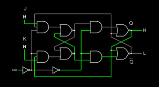
Here's a complete JK flip-flop using two latch stages. This is commonly known as a "master-slave" (not really PC anymore) or "edge-triggered" JK flip-flop:

enter image description here

JK flip-flop using a pair of latches

As expected, the flop toggles on clock rise when both J and K are high.

Ugh. This again. tl, dr: The gated JK latch is a junk circuit and should not be used in a modern design. It's useless, except as a lesson of how not to design a latch.

Let's start with the The Ben Eater drawing. It's wrong - the feedbacks are crossed.

enter image description here

Ben Eater's broken version in Falstad

As you can see, this doesn't do anything.

So let's fix the feedback connections...

enter image description here

try it here with Falstad. It oscillates

... uh oh, there's a problem. We now have a working (sorta) gated JK latch, and we can see this behavior:

  • J, K = 0, 0: hold
  • J, K = 1, 0: Q = 1, Qbar = 0 at clock rise
  • J, K = 0, 1: Q = 0, Qbar = 1 at clock rise
  • J, K = 1, 1: very bad things when clock is high

The expected Q/Qbar toggle with J and K high doesn't happen. It oscillates!

Why? When both the J and K inputs are ‘1’ and clock is high, the two NORs and ANDs form a pair of inverters wired head-to-tail. With all the inputs high, you have a ring oscillator, a useful circuit by itself (it's used in PLLs for example), but not here. This oscillation is sometimes called "race-around", and was a (mis-)feature of early JK flop logic designs (yes, including Jack Kilby's).

Instead, we want the state to change only at clock rise. We have two ways to do that:

  • use a rising-edge detect on the clock that generates a pulse narrow enough to suppress the 'race around'
  • use two gated latch stages, each controlled by opposite clock phase

The first approach is a hack to save gates. While it worked with early logic that was slow, no one in their right mind would do a clocked JK flop that way today.

The second, two-stage approach is what's used in real chips, even early TTL devices like the 74xx73.

Here's a complete JK flip-flop using two latch stages. This is commonly known as a "master-slave" (not really PC anymore) or "edge-triggered" JK flip-flop:

enter image description here

JK flip-flop using a pair of latches

As expected, the flop toggles on clock rise when both J and K are high.
Ugh. This again. tl, dr: The gated JK latch is a junk circuit and should not be used in a modern design. It's useless, except as a lesson of how not to design a latch.

Let's start with the The Ben Eater drawing. It's wrong - the feedbacks are crossed.

enter image description here

Ben Eater's broken version in Falstad

As you can see, this doesn't do anything.

So let's fix the feedback connections...

enter image description here

try it here with Falstad. It oscillates

... uh oh, there's a problem. We now have a working (sorta) gated JK latch, and we can see this behavior:

  • J, K = 0, 0: hold
  • J, K = 1, 0: Q = 1, Qbar = 0 at clock rise
  • J, K = 0, 1: Q = 0, Qbar = 1 at clock rise
  • J, K = 1, 1: very bad things when clock is high

The expected Q/Qbar toggle with J and K high doesn't happen. It oscillates!

Why? When both the J and K inputs are ‘1’ and clock is high, the two NORs and ANDs form a pair of inverters wired head-to-tail. With all the inputs high, you have a ring oscillator, a useful circuit by itself (it's used in PLLs for example), but not here. This oscillation is sometimes called "race-around", and was a (mis-)feature of early JK flop logic designs (yes, including Jack Kilby's).

Instead, we want the state to change only at clock rise. We have two ways to do that:

  • use a rising-edge detect on the clock that generates a pulse narrow enough to suppress the 'race around'
  • use two gated latch stages, each controlled by opposite clock phase

The first approach is a hack to save gates. While it worked with early logic that was slow, no one in their right mind would do a clocked JK flop that way today.

Nevertheless, in the interest of completeness, here's an example using a rising-edge pulse detector on the clock:

enter image description here

Falstad sim of JK latch with rising-edge pulse detect

The second, two-stage approach is what's used in real chips, even early TTL devices like the 74xx73.

Here's a complete JK flip-flop using two latch stages. This is commonly known as a "master-slave" (not really PC anymore) or "edge-triggered" JK flip-flop:

enter image description here

JK flip-flop using a pair of latches

As expected, the flop toggles on clock rise when both J and K are high.
added 176 characters in body
Source Link
hacktastical
  • 58.4k
  • 2
  • 54
  • 166

Ugh. This again. tl, dr: The gated JK latch is a junk circuit and should not be used in a modern design. It's useless, except as a lesson of how not to design a latch.

Let's start with the The Ben Eater drawing. It's wrong - the feedbacks are crossed.

enter image description here

Ben Eater's broken version in Falstad

As you can see, this doesn't do anything.

So let's fix the feedback connections...

enter image description here

try it here with Falstad. It oscillates

... uh oh, there's a problem. We now have a working (sorta) gated JK latch, and we can see this behavior:

  • J, K = 0, 0: hold
  • J, K = 1, 0: Q = 1, Qbar = 0 at clock rise
  • J, K = 0, 1: Q = 0, Qbar = 1 at clock rise
  • J, K = 1, 1: very bad things when clock is high

The expected Q/Qbar toggle with J and K high doesn't happen. It oscillates!

Why? When both the J and K inputs are ‘1’ and clock is high, the two NORs and ANDs form a pair of inverters wired head-to-tail. With all the inputs high, you have a ring oscillator, a useful circuit by itself (it's used in PLLs for example), but not here. This oscillation is sometimes called "race-around", and was a (mis-)feature of early JK flop logic designs (yes, including Jack Kilby's).

Instead, we want the state to change only at clock rise. We have two ways to do that:

  • use a rising-edge detect on the clock that generates a pulse narrow enough to suppress the 'race around'
  • use two gated latch stages, each controlled by opposite clock phase

The first approach is a hack to save gates. While it worked with early logic that was slow, no one in their right mind would do ita clocked JK flop that way today.

The second, two-stage approach is what's used in real chips, even early TTL devices like the 74xx73.

Here's a complete JK flip-flop using two latch stages. This is commonly known as a "master-slave" (not really PC anymore) or "edge-triggered" JK flip-flop:

enter image description here

JK flip-flop using a pair of latches

As expected, the flop toggles on clock rise when both J and K are high.
Ugh. This again. tl, dr: The gated JK latch is a junk circuit and should not be used in a modern design. It's useless, except as a lesson of how not to design a latch.

Let's start with the The Ben Eater drawing. It's wrong - the feedbacks are crossed.

enter image description here

Ben Eater's broken version in Falstad

As you can see, this doesn't do anything.

So let's fix the feedback connections...

enter image description here

try it here with Falstad. It oscillates

... uh oh, there's a problem. We now have a working (sorta) gated JK latch, and we can see this behavior:

  • J, K = 0, 0: hold
  • J, K = 1, 0: Q = 1, Qbar = 0 at clock rise
  • J, K = 0, 1: Q = 0, Qbar = 1 at clock rise
  • J, K = 1, 1: very bad things when clock is high

The expected Q/Qbar toggle with J and K high doesn't happen. It oscillates!

Why? When both the J and K inputs are ‘1’ and clock is high, the two NORs and ANDs form a pair of inverters wired head-to-tail. With all the inputs high, you have a ring oscillator, a useful circuit by itself (it's used in PLLs for example), but not here. This oscillation is sometimes called "race-around", and was a (mis-)feature of early JK flop logic designs (yes, including Jack Kilby's).

Instead, we want the state to change only at clock rise. We have two ways to do that:

  • use a rising-edge detect that generates a pulse narrow enough to suppress the 'race around'
  • use two gated latch stages, each controlled by opposite clock phase

The first approach is a hack to save gates. While it worked with early logic that was slow, no one in their right mind would do it that way today.

The second, two-stage approach is what's used in real chips, even early TTL devices like the 74xx73.

Here's a complete JK flip-flop using two latch stages. This is commonly known as a "master-slave" (not really PC anymore) or "edge-triggered" JK flip-flop:

enter image description here

JK flip-flop using a pair of latches

As expected, the flop toggles on clock rise when both J and K are high.
Ugh. This again. tl, dr: The gated JK latch is a junk circuit and should not be used in a modern design. It's useless, except as a lesson of how not to design a latch.

Let's start with the The Ben Eater drawing. It's wrong - the feedbacks are crossed.

enter image description here

Ben Eater's broken version in Falstad

As you can see, this doesn't do anything.

So let's fix the feedback connections...

enter image description here

try it here with Falstad. It oscillates

... uh oh, there's a problem. We now have a working (sorta) gated JK latch, and we can see this behavior:

  • J, K = 0, 0: hold
  • J, K = 1, 0: Q = 1, Qbar = 0 at clock rise
  • J, K = 0, 1: Q = 0, Qbar = 1 at clock rise
  • J, K = 1, 1: very bad things when clock is high

The expected Q/Qbar toggle with J and K high doesn't happen. It oscillates!

Why? When both the J and K inputs are ‘1’ and clock is high, the two NORs and ANDs form a pair of inverters wired head-to-tail. With all the inputs high, you have a ring oscillator, a useful circuit by itself (it's used in PLLs for example), but not here. This oscillation is sometimes called "race-around", and was a (mis-)feature of early JK flop logic designs (yes, including Jack Kilby's).

Instead, we want the state to change only at clock rise. We have two ways to do that:

  • use a rising-edge detect on the clock that generates a pulse narrow enough to suppress the 'race around'
  • use two gated latch stages, each controlled by opposite clock phase

The first approach is a hack to save gates. While it worked with early logic that was slow, no one in their right mind would do a clocked JK flop that way today.

The second, two-stage approach is what's used in real chips, even early TTL devices like the 74xx73.

Here's a complete JK flip-flop using two latch stages. This is commonly known as a "master-slave" (not really PC anymore) or "edge-triggered" JK flip-flop:

enter image description here

JK flip-flop using a pair of latches

As expected, the flop toggles on clock rise when both J and K are high.

added 176 characters in body
Source Link
hacktastical
  • 58.4k
  • 2
  • 54
  • 166

Ugh. This again. tl, dr: The gated JK latch is a junk circuit and should not be used in a modern design. It's useless, except as a lesson of how not to design a latch.

Let's start with the The Ben Eater drawing is. It's wrong - the feedbacks are crossed.

enter image description here

here's BenBen Eater's broken version in Falstad

enter image description here As you can see, this doesn't do anything.

Even withSo let's fix the ‘corrected’ drawing below, know that this is a latch, and it doesn’t work correctlyfeedback connections. The output definitely does not toggle with J and K high..

enter image description here

try it here with Falstad. It oscillates

enter image description here

tl... uh oh, dr: It’sthere's a junk circuitproblem. Useless, except asWe now have a lesson of howworking (sorta) notgated JK latch to design a latch, and we can see this behavior:

  • J, K = 0, 0: hold
  • J, K = 1, 0: Q = 1, Qbar = 0 at clock rise
  • J, K = 0, 1: Q = 0, Qbar = 1 at clock rise
  • J, K = 1, 1: very bad things when clock is high

The expected Q/Qbar toggle with J and K high doesn't happen. It oscillates!

Why? When both the J and K inputs are ‘1’ the output oscillates during the time that theand clock pulse is high. This is because, the two NORs and ANDs form a pair of inverters wired head-to-tail. That, folksWith all the inputs high, isyou have a ring oscillator, a useful circuit by itself (it's used in PLLs for example), but not here. This oscillation is sometimes called "race-around", and was a (mis-)feature of early JK flop logic designs (yes, including Jack Kilby's).

And finallyInstead, here'swe want the state to change only at clock rise. We have two ways to do that:

  • use a rising-edge detect that generates a pulse narrow enough to suppress the 'race around'
  • use two gated latch stages, each controlled by opposite clock phase

The first approach is a correcthack to save gates. While it worked with early logic that was slow, no one in their right mind would do it that way today.

The second, two-stage approach is what's used in real chips, even early TTL devices like the 74xx73.

Here's a complete JK flip-flop using a pair of latches (commonlytwo latch stages. This is commonly known as a "master-slave" (not really PC anymore) or "edge-triggered" JK flip-flop):

enter image description here

JK flip-flop using a pair of latches

enter image description here

The As expected, the flop toggles as expectedon clock rise when both J and K are high.

Ugh. This again. The Ben Eater drawing is wrong - the feedbacks are crossed.

here's Ben Eater's broken version in Falstad

enter image description here

Even with the ‘corrected’ drawing below, know that this is a latch, and it doesn’t work correctly. The output definitely does not toggle with J and K high.

try it here with Falstad. It oscillates

enter image description here

tl, dr: It’s a junk circuit. Useless, except as a lesson of how not to design a latch.

Why? When both inputs are ‘1’ the output oscillates during the time that the clock pulse is high. This is because the two NORs and ANDs form a pair of inverters wired head-to-tail. That, folks, is a ring oscillator, a useful circuit by itself, but not here.

And finally, here's a correct JK flip-flop using a pair of latches (commonly known as "master-slave" or "edge-triggered" JK flip-flop):

JK flip-flop using a pair of latches

enter image description here

The flop toggles as expected when both J and K are high.

Ugh. This again. tl, dr: The gated JK latch is a junk circuit and should not be used in a modern design. It's useless, except as a lesson of how not to design a latch.

Let's start with the The Ben Eater drawing. It's wrong - the feedbacks are crossed.

enter image description here

Ben Eater's broken version in Falstad

As you can see, this doesn't do anything.

So let's fix the feedback connections...

enter image description here

try it here with Falstad. It oscillates

... uh oh, there's a problem. We now have a working (sorta) gated JK latch, and we can see this behavior:

  • J, K = 0, 0: hold
  • J, K = 1, 0: Q = 1, Qbar = 0 at clock rise
  • J, K = 0, 1: Q = 0, Qbar = 1 at clock rise
  • J, K = 1, 1: very bad things when clock is high

The expected Q/Qbar toggle with J and K high doesn't happen. It oscillates!

Why? When both the J and K inputs are ‘1’ and clock is high, the two NORs and ANDs form a pair of inverters wired head-to-tail. With all the inputs high, you have a ring oscillator, a useful circuit by itself (it's used in PLLs for example), but not here. This oscillation is sometimes called "race-around", and was a (mis-)feature of early JK flop logic designs (yes, including Jack Kilby's).

Instead, we want the state to change only at clock rise. We have two ways to do that:

  • use a rising-edge detect that generates a pulse narrow enough to suppress the 'race around'
  • use two gated latch stages, each controlled by opposite clock phase

The first approach is a hack to save gates. While it worked with early logic that was slow, no one in their right mind would do it that way today.

The second, two-stage approach is what's used in real chips, even early TTL devices like the 74xx73.

Here's a complete JK flip-flop using two latch stages. This is commonly known as a "master-slave" (not really PC anymore) or "edge-triggered" JK flip-flop:

enter image description here

JK flip-flop using a pair of latches

As expected, the flop toggles on clock rise when both J and K are high.

added 176 characters in body
Source Link
hacktastical
  • 58.4k
  • 2
  • 54
  • 166
Loading
added 176 characters in body
Source Link
hacktastical
  • 58.4k
  • 2
  • 54
  • 166
Loading
deleted 779 characters in body
Source Link
hacktastical
  • 58.4k
  • 2
  • 54
  • 166
Loading
added 2589 characters in body
Source Link
hacktastical
  • 58.4k
  • 2
  • 54
  • 166
Loading
added 1770 characters in body
Source Link
hacktastical
  • 58.4k
  • 2
  • 54
  • 166
Loading
added 9 characters in body
Source Link
hacktastical
  • 58.4k
  • 2
  • 54
  • 166
Loading
added 161 characters in body
Source Link
hacktastical
  • 58.4k
  • 2
  • 54
  • 166
Loading
deleted 1739 characters in body
Source Link
hacktastical
  • 58.4k
  • 2
  • 54
  • 166
Loading
deleted 1739 characters in body
Source Link
hacktastical
  • 58.4k
  • 2
  • 54
  • 166
Loading
Source Link
hacktastical
  • 58.4k
  • 2
  • 54
  • 166
Loading