added schematic image
Source Link

After doing some reading online, it seems that you can't really build a step-down converter with only a filtering capacitor and without an inductor, because the losses occuring during charging of the capacitor would lead to low efficiency.

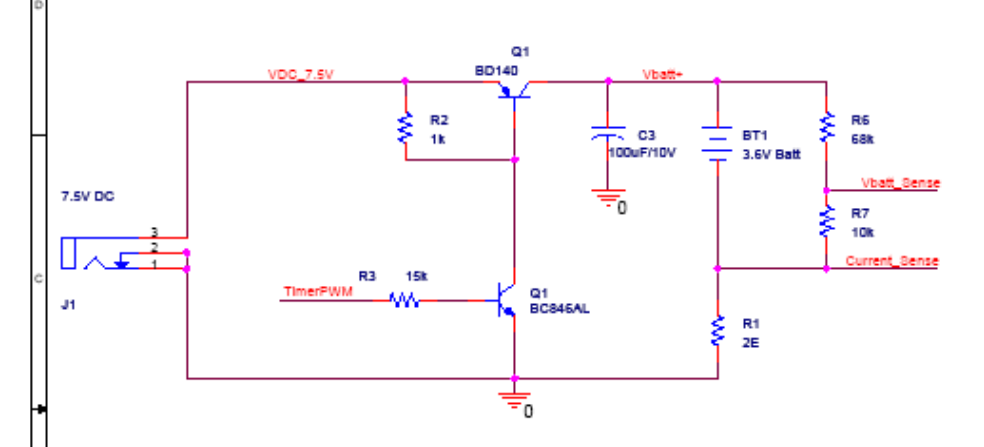
However, I'm looking at a application note from Zilog: "AN0259 - Low-Cost NiMH Battery Charger Using the Z8F0830": https://www.zilog.com/docs/z8encorexp/appnotes/AN0259.pdf which is using exactly that circuit - a capacitor is charged with a 10 kHz PWM signal, which in turn charges the NiMH battery. No inductor is present in the circuit.

What enter image description here What makes this circuit work in that situation? Or maybe it acts as I described above - it has high losses, but the designers just roll with it?
After doing some reading online, it seems that you can't really build a step-down converter with only a filtering capacitor and without an inductor, because the losses occuring during charging of the capacitor would lead to low efficiency.

However, I'm looking at a application note from Zilog: "AN0259 - Low-Cost NiMH Battery Charger Using the Z8F0830": https://www.zilog.com/docs/z8encorexp/appnotes/AN0259.pdf which is using exactly that circuit - a capacitor is charged with a 10 kHz PWM signal, which in turn charges the NiMH battery. No inductor is present in the circuit.

What makes this circuit work in that situation? Or maybe it acts as I described above - it has high losses, but the designers just roll with it?

After doing some reading online, it seems that you can't really build a step-down converter with only a filtering capacitor and without an inductor, because the losses occuring during charging of the capacitor would lead to low efficiency.

However, I'm looking at a application note from Zilog: "AN0259 - Low-Cost NiMH Battery Charger Using the Z8F0830": https://www.zilog.com/docs/z8encorexp/appnotes/AN0259.pdf which is using exactly that circuit - a capacitor is charged with a 10 kHz PWM signal, which in turn charges the NiMH battery. No inductor is present in the circuit. enter image description here What makes this circuit work in that situation? Or maybe it acts as I described above - it has high losses, but the designers just roll with it?

Source Link

Buck converter without inductor in a NiMH charger (Zilog AN0259 application note)

After doing some reading online, it seems that you can't really build a step-down converter with only a filtering capacitor and without an inductor, because the losses occuring during charging of the capacitor would lead to low efficiency.

However, I'm looking at a application note from Zilog: "AN0259 - Low-Cost NiMH Battery Charger Using the Z8F0830": https://www.zilog.com/docs/z8encorexp/appnotes/AN0259.pdf which is using exactly that circuit - a capacitor is charged with a 10 kHz PWM signal, which in turn charges the NiMH battery. No inductor is present in the circuit.

What makes this circuit work in that situation? Or maybe it acts as I described above - it has high losses, but the designers just roll with it?