added 13 characters in body
Source Link
JRE
  • 73.6k
  • 10
  • 112
  • 195

I'm a mechanical engineer, who has the luck to design an easy transimpedance amplifier circuit to convert the current of ana photodiode to a voltage between 0 and 5V (without really knowing anything about it.)

I used this reference design from Texas Instruments and did the calculations.

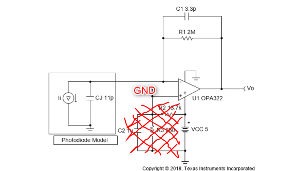
After some weired results with the voltage divider in place, I changed the design to the one you can see in the next picture.

(The values of the components are different in my design.)

enter image description here

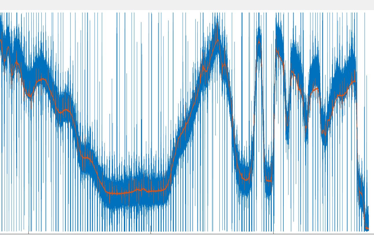
I ended up with some "useful" measurements, which showed more or less the same signal pattern compared to a professionally built transimpedance amplifier. See picture below. Blue line is my DIY-version, orange line is the bought amplifier.

As you can see, there is a lot of noise in my design. I'm not really deep into electronics so I don't know how to improve the performance.

Can somebody give me some advice how I can reduce the noise?

FYI: I used this opamp.

enter image description here

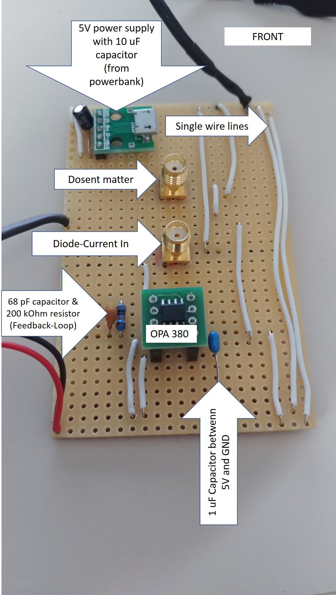
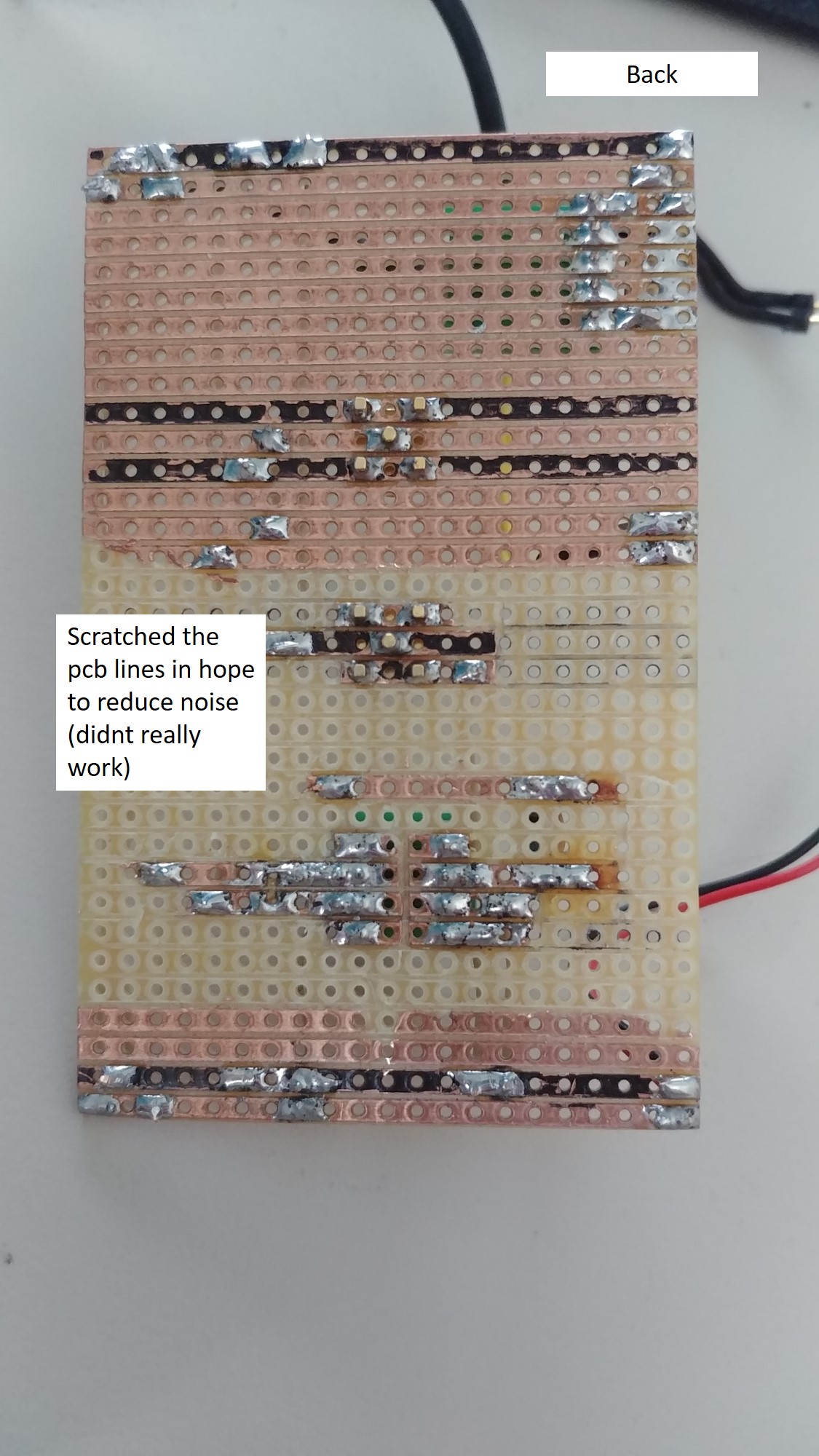
EDIT: I added the pitures of my PCB + the values of the components. When I read through the comments I realized that there is more to consider than I expected. I dont need a super low noise Trans-amptransimpedance amplifier, but lower noise would be great!. Are there any easy fixes, which iI can use without additonal curcitry?

enter image description here enter image description here

I'm a mechanical engineer, who has the luck to design an easy transimpedance amplifier circuit to convert the current of an photodiode to a voltage between 0 and 5V (without really knowing anything about it.)

I used this reference design from Texas Instruments and did the calculations.

After some weired results with the voltage divider in place, I changed the design to the one you can see in the next picture.

(The values of the components are different in my design.)

enter image description here

I ended up with some "useful" measurements, which showed more or less the same signal pattern compared to a professionally built transimpedance amplifier. See picture below. Blue line is my DIY-version, orange line is the bought amplifier.

As you can see, there is a lot of noise in my design. I'm not really deep into electronics so I don't know how to improve the performance.

Can somebody give me some advice how I can reduce the noise?

FYI: I used this opamp.

enter image description here

EDIT: I added the pitures of my PCB + the values of the components. When I read through the comments I realized that there is more to consider than I expected. I dont need a super low noise Trans-amp, but lower noise would be great! Are there any easy fixes, which i can use without additonal curcitry?

enter image description here enter image description here

I'm a mechanical engineer, who has the luck to design an easy transimpedance amplifier circuit to convert the current of a photodiode to a voltage between 0 and 5V (without really knowing anything about it.)

I used this reference design from Texas Instruments and did the calculations.

After some weired results with the voltage divider in place, I changed the design to the one you can see in the next picture.

(The values of the components are different in my design.)

enter image description here

I ended up with some "useful" measurements, which showed more or less the same signal pattern compared to a professionally built transimpedance amplifier. See picture below. Blue line is my DIY-version, orange line is the bought amplifier.

As you can see, there is a lot of noise in my design. I'm not really deep into electronics so I don't know how to improve the performance.

Can somebody give me some advice how I can reduce the noise?

FYI: I used this opamp.

enter image description here

EDIT: I added the pitures of my PCB + the values of the components. When I read through the comments I realized that there is more to consider than I expected. I dont need a super low noise transimpedance amplifier, but lower noise would be great. Are there any easy fixes which I can use without additonal curcitry?
enter image description here enter image description here

added 482 characters in body
Source Link

I'm a mechanical engineer, who has the luck to design an easy transimpedance amplifier circuit to convert the current of an photodiode to a voltage between 0 and 5V (without really knowing anything about it.)

I used this reference design from Texas Instruments and did the calculations.

After some weired results with the voltage divider in place, I changed the design to the one you can see in the next picture.

(The values of the components are different in my design.)

enter image description here

I ended up with some "useful" measurements, which showed more or less the same signal pattern compared to a professionally built transimpedance amplifier. See picture below. Blue line is my DIY-version, orange line is the bought amplifier.

As you can see, there is a lot of noise in my design. I'm not really deep into electronics so I don't know how to improve the performance.

Can somebody give me some advice how I can reduce the noise?

FYI: I used this opamp.

enter image description here

EDIT: I added the pitures of my PCB + the values of the components. When I read through the comments I realized that there is more to consider than I expected. I dont need a super low noise Trans-amp, but lower noise would be great! Are there any easy fixes, which i can use without additonal curcitry?
enter image description here enter image description here

I'm a mechanical engineer, who has the luck to design an easy transimpedance amplifier circuit to convert the current of an photodiode to a voltage between 0 and 5V (without really knowing anything about it.)

I used this reference design from Texas Instruments and did the calculations.

After some weired results with the voltage divider in place, I changed the design to the one you can see in the next picture.

(The values of the components are different in my design.)

enter image description here

I ended up with some "useful" measurements, which showed more or less the same signal pattern compared to a professionally built transimpedance amplifier. See picture below. Blue line is my DIY-version, orange line is the bought amplifier.

As you can see, there is a lot of noise in my design. I'm not really deep into electronics so I don't know how to improve the performance.

Can somebody give me some advice how I can reduce the noise?

FYI: I used this opamp.

enter image description here

EDIT: I added the pitures of my PCB + the values of the components. When I read through the comments I realized that there is more to consider than I expected. I dont need a super low noise Trans-amp, but lower noise would be great! Are there any easy fixes, which i can use without additonal curcitry?
enter image description here enter image description here

deleted 226 characters in body; edited title
Source Link
JRE
  • 73.6k
  • 10
  • 112
  • 195

Design of ana simple Transimpedancetransimpedance amplifier for large area photodiode

i'm anI'm a mechanical engineer, who has the luck to design an easy tranimpedancetransimpedance amplifier circutrycircuit to convert the current of an photodiode to a voltage between 0 and 5V (without really knowing anything about it). I used this reference desing from Texas Instruments and did the calculations.)

(https://www.ti.com/lit/an/sboa220a/sboa220a.pdf?ts=1594038188275&ref_url=https%253A%252F%252Fwww.ti.com%252Fdesign-resources%252Fdesign-tools-simulation%252Fanalog-circuits%252Famplifier-circuits.html) I used this reference design from Texas Instruments and did the calculations.

After some wieredweired results with the voltage divider in place, iI changed the design to the one you can see in the next picture.   

(theThe values of the components are different in my design.)   

enter image description here

I ended up with some "useful" meassurmentsmeasurements, which showed more or less the same signal pattern compardedcompared to one professionellya professionally built transimpedance amplifier. See picture below. Blue line is my DIY-version, orange line is the bought amplifier.

As you can see, there ist alotis a lot of noise in my design. ImI'm not really deep into electronics so i dontI don't know how to improve the performance. 

Can anybodysomebody give me some advice, how iI can reduce the noise?

FyiFYI: I used this OpAmp: (https://www.ti.com/lit/ds/symlink/opa380.pdf?ts=1598799996130&ref_url=https%253A%252F%252Fwww.google.com%252F)

Thanks alot!this opamp.

enter image description here

Design of an simple Transimpedance amplifier for large area photodiode

i'm an mechanical engineer, who has the luck to design an easy tranimpedance amplifier circutry to convert the current of an photodiode to a voltage between 0 and 5V (without really knowing anything about it). I used this reference desing from Texas Instruments and did the calculations.

(https://www.ti.com/lit/an/sboa220a/sboa220a.pdf?ts=1594038188275&ref_url=https%253A%252F%252Fwww.ti.com%252Fdesign-resources%252Fdesign-tools-simulation%252Fanalog-circuits%252Famplifier-circuits.html)

After some wiered results with the voltage divider in place, i changed the design to the one you can see in the next picture.  (the values of the components are different in my design)  enter image description here

I ended up with some "useful" meassurments, which showed more or less the same signal pattern comparded to one professionelly built transimpedance amplifier. See picture below. Blue line is my DIY-version, orange line is the bought amplifier.

As you can see, there ist alot of noise in my design. Im not really deep into electronics so i dont know how to improve the performance. Can anybody give me some advice, how i can reduce the noise?

Fyi: I used this OpAmp: (https://www.ti.com/lit/ds/symlink/opa380.pdf?ts=1598799996130&ref_url=https%253A%252F%252Fwww.google.com%252F)

Thanks alot!

enter image description here

Design of a simple transimpedance amplifier for large area photodiode

I'm a mechanical engineer, who has the luck to design an easy transimpedance amplifier circuit to convert the current of an photodiode to a voltage between 0 and 5V (without really knowing anything about it.)

I used this reference design from Texas Instruments and did the calculations.

After some weired results with the voltage divider in place, I changed the design to the one you can see in the next picture. 

(The values of the components are different in my design.) 

enter image description here

I ended up with some "useful" measurements, which showed more or less the same signal pattern compared to a professionally built transimpedance amplifier. See picture below. Blue line is my DIY-version, orange line is the bought amplifier.

As you can see, there is a lot of noise in my design. I'm not really deep into electronics so I don't know how to improve the performance. 

Can somebody give me some advice how I can reduce the noise?

FYI: I used this opamp.

enter image description here

Source Link
Loading