I'm a mechanical engineer, who has the luck to design an easy transimpedance amplifier circuit to convert the current of an photodiode to a voltage between 0 and 5V (without really knowing anything about it.)
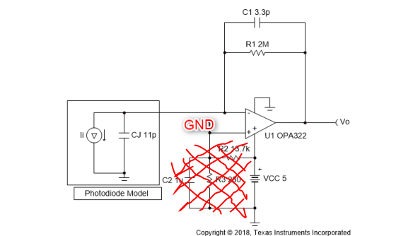
I used this reference design from Texas Instruments and did the calculations.
After some weired results with the voltage divider in place, I changed the design to the one you can see in the next picture.
(The values of the components are different in my design.)
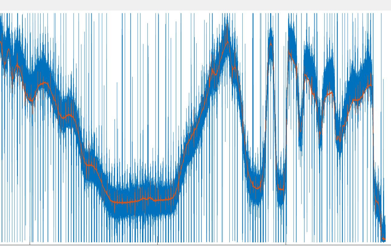
I ended up with some "useful" measurements, which showed more or less the same signal pattern compared to a professionally built transimpedance amplifier. See picture below. Blue line is my DIY-version, orange line is the bought amplifier.
As you can see, there is a lot of noise in my design. I'm not really deep into electronics so I don't know how to improve the performance.
Can somebody give me some advice how I can reduce the noise?
FYI: I used this opamp.
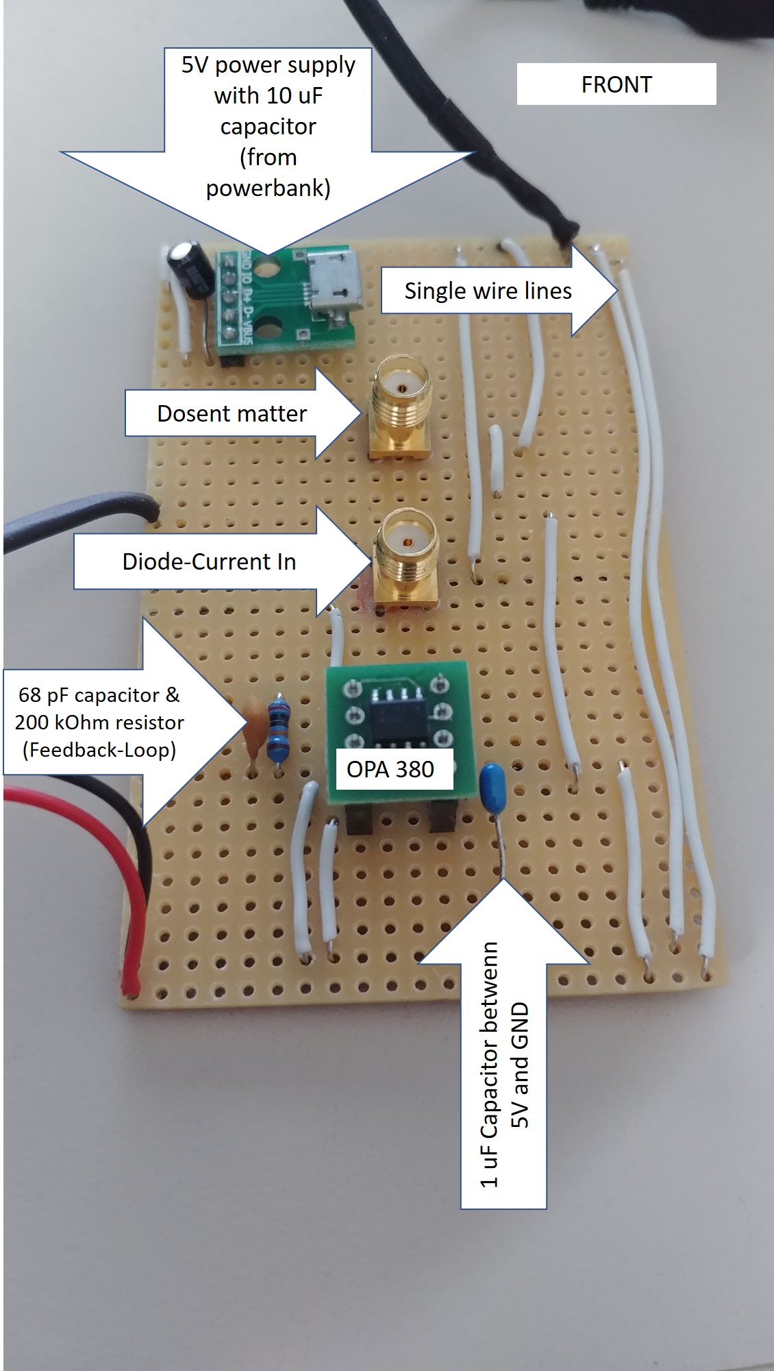
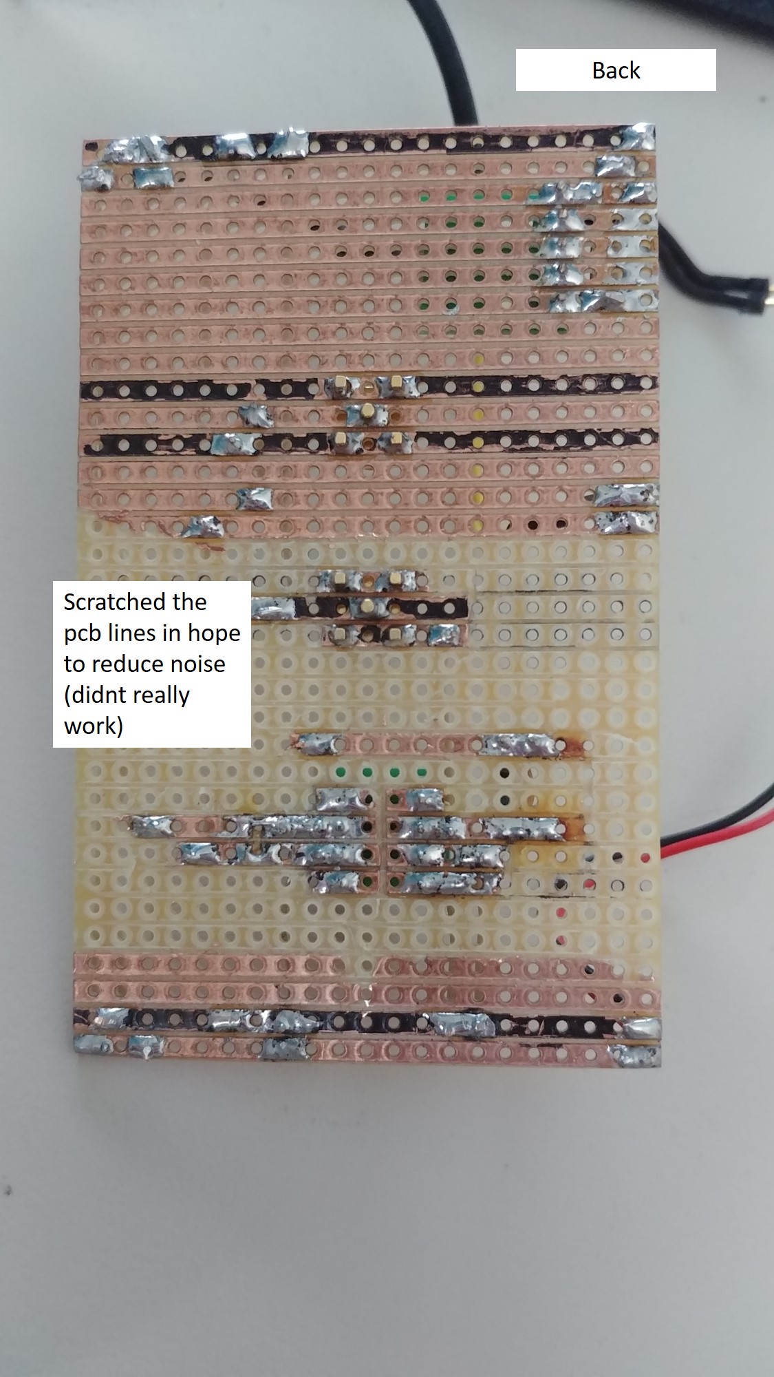
EDIT: I added the pitures of my PCB + the values of the components. When I read through the comments I realized that there is more to consider than I expected. I dont need a super low noise Trans-amp, but lower noise would be great! Are there any easy fixes, which i can use without additonal curcitry?


