Commonmark migration
Source Link

##Power source:

Power source:

##Power source:

Power source:

added 2062 characters in body; edited tags; edited title
Source Link
alan
  • 817
  • 2
  • 8
  • 15

Is On-die 220 V AC capable SMPS possible? Simplest Way to step down the 220AC with more than 10% efficiency

I want to design a tiny single packaged mains-powered temperature sensor. Possibly as a multi-chip module (MCM).

And I checked a lot about the power converter, mainly they are PCB package, and they have very big capacitors in or around. I hope my voltage converter device could be a single chip which can connect sensor chip, so I can pack them on one tiny pcb board which is small and thin, and then add two prongs to plug into the wallPCB board.

  1. Operates (Iq) between 1VDC, 10mA and 3VDC, 30mA
  2. It is a 65nm Samgsung fabraction process. So it is very small. I may not design the power source in this 65nm process, but I hope I can design it in CMOS fabraction process.

Power##Power source:

  1. around 110V ~ 220V mains powered (single-phase, actually I am in Korea, and around 220V is enough, if the small range can help me small size my design, around 220V is OK for me. )

  2. Operation without a secondary source (batt, bulk cap, et. al.) desired to minimize size.

  3. The efficiency demanding is just >10% and that is enough for me.

AsksIdeas now

  1. What connector strategy would be appropriate for minimum size without compromising safety?
  2. Which architectural approaches should I consider to minimize the size of the final solution so as to possibly fit the entire solution on a single die?

I was intended to design my power converter into a small chip, thanks alot for people's suggestions . I think about charge pump, and different IC modules, the RF powerharvesting, and the possibility for implementing such a device on nm Si process. Above all, microchips that can convert 220V ac to low dc is big-size for me, and also have lots big caps around module; charge pump from Olin's idea, I dont think I can design diode that can support high-voltage on chip, if not on chip, it will be big size(I think); for powerharvesting, I did some research before, and honestly it is good, but RF energy is not very solid, and there are some limitations about the distance. So I go back to the original ideas how to convert voltage. Hope your guys can check if they are right. I will use some regulating stuff(off chip) to regulate the voltage at last, so i just wanna check if the thoughts are right.

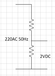
PS1> Linear with the resistors. Input 220Vac to the two resistors,one is 1Mohm, the other is around 10Kohm,figure below: My final problem
enter image description here

I know the efficiency is verylow, howabout 1%, so I drop it. But it is my earliest idea.

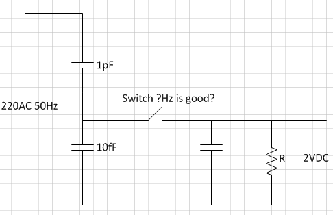
2> linear with the capacitor. Since the first way efficiency is so low, I wonder can I really avoid those biguse two capacitors to replace the resistors, and(figures below) one cap is 1pf, the other is 10fF (the exact values are not certain).
enter image description here

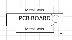
also I wanna design the big capacitor on my pcb board by myself like figure below,so I can mini-size. If the cap value is not big, I can design it in a small wayon chip.
enter image description here

First I dont know if the fundamental of circuit ? At some point(the first figure) will work or not, because I really wantnever see this before, but as I know, I hope it works. Assume it works, how to design it in a nm processexactly ( I mean how to design the cap value properly and how to choose the switch frequency properly). So

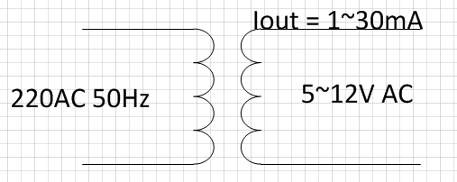
3> The conventional linear isolating converter:
enter image description here

My question is, in this conventional way, the output current in other designs usually needs big, so the transformer is big, but I dontjust need it very small(1mA~30mA), so according to your view, how big things.it will be, I need some brief and brilliantknow little about transformer design ideas. the voltage ratio is 45:1, and the current is 1:45, how many coils on both sides are good ? How big it will.

PSS: Some people help me with some good ideas(thanksif the transformer above is not so big, Furthermore, my design method for all of themthe transformer is improved, and I broke some rules here wanna design transformer on PCB board by myself, like figures below:
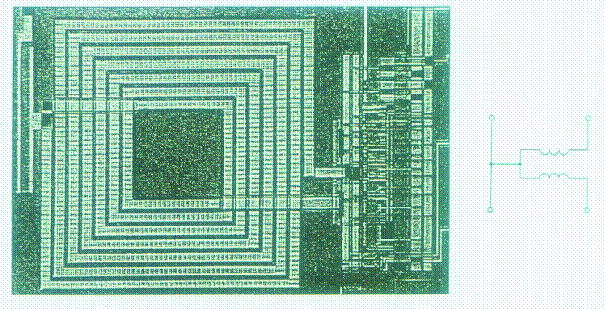
enter image description here

in my first figure, I just use one stage transformer, if size is big to design 220V-5V converting, maybe I can design two or more stages to convert like 220V-48V-5V. I hope the newbie here wonttransformer (each stage, hope one stage is enough) is less than 1cm×1cm. If that is possible, I WILL do it again. and sorry forAnd I think the communityefficiency is good, and some peoplealso safe.

Above all, I was rude.want to improve my design in the No 2 and No 3 method, but I dont know if my thoughts are right or not. Ready to get judgement now.)

Is On-die 220 V AC capable SMPS possible?

I want to design a tiny single packaged mains-powered temperature sensor. Possibly as a multi-chip module (MCM).

And I checked a lot about the power converter, mainly they are PCB package, and they have very big capacitors in or around. I hope my voltage converter device could be a single chip which can connect sensor chip, so I can pack them on one tiny pcb board which is small and thin, and then add two prongs to plug into the wall.

  1. Operates (Iq) between 1VDC, 10mA and 3VDC, 30mA
  2. It is a 65nm Samgsung fabraction process. So it is very small. I may not design the power source in this 65nm process, but I hope I can design it in CMOS fabraction process.

Power source:

  1. around 110V ~ 220V mains powered (single-phase, actually I am in Korea, and around 220V is enough, if the small range can help me small size my design, around 220V is OK for me. )

  2. Operation without a secondary source (batt, bulk cap, et. al.) desired to minimize size.

  3. The efficiency demanding is just >10% and that is enough for me.

Asks

  1. What connector strategy would be appropriate for minimum size without compromising safety?
  2. Which architectural approaches should I consider to minimize the size of the final solution so as to possibly fit the entire solution on a single die?

PS: My final problem is, how can I really avoid those big capacitors, and design it in a small way ? At some point, I really want to design it in a nm process. So I dont need big things. I need some brief and brilliant design ideas.

PSS: Some people help me with some good ideas(thanks for all of them, and I broke some rules here, hope the newbie here wont do it again. and sorry for the community, and some people, I was rude...)

Simplest Way to step down the 220AC with more than 10% efficiency

I want to design a tiny single packaged mains-powered temperature sensor. Possibly as a multi-chip module (MCM) on one small PCB board.

  1. Operates (Iq) between 1VDC, 10mA and 3VDC, 30mA
  2. It is a 65nm Samgsung fabraction process. So it is very small.

##Power source:

  1. around 220V mains powered (single-phase)

  2. Operation without a secondary source (batt, bulk cap, et. al.) desired to minimize size.

  3. The efficiency demanding is just >10% and that is enough for me.

Ideas now

I was intended to design my power converter into a small chip, thanks alot for people's suggestions . I think about charge pump, and different IC modules, the RF powerharvesting, and the possibility for implementing such a device on nm Si process. Above all, microchips that can convert 220V ac to low dc is big-size for me, and also have lots big caps around module; charge pump from Olin's idea, I dont think I can design diode that can support high-voltage on chip, if not on chip, it will be big size(I think); for powerharvesting, I did some research before, and honestly it is good, but RF energy is not very solid, and there are some limitations about the distance. So I go back to the original ideas how to convert voltage. Hope your guys can check if they are right. I will use some regulating stuff(off chip) to regulate the voltage at last, so i just wanna check if the thoughts are right.

1> Linear with the resistors. Input 220Vac to the two resistors,one is 1Mohm, the other is around 10Kohm,figure below:

enter image description here

I know the efficiency is verylow, about 1%, so I drop it. But it is my earliest idea.

2> linear with the capacitor. Since the first way efficiency is so low, I wonder can I use two capacitors to replace the resistors, (figures below) one cap is 1pf, the other is 10fF (the exact values are not certain).

enter image description here

also I wanna design the big capacitor on my pcb board by myself like figure below,so I can mini-size. If the cap value is not big, I can design it on chip.

enter image description here

First I dont know if the fundamental of circuit (the first figure) will work or not, because I never see this before, but as I know, I hope it works. Assume it works, how to design it exactly ( I mean how to design the cap value properly and how to choose the switch frequency properly).

3> The conventional linear isolating converter:

enter image description here

My question is, in this conventional way, the output current in other designs usually needs big, so the transformer is big, but I just need it very small(1mA~30mA), so according to your view, how big it will be, I know little about transformer design. the voltage ratio is 45:1, and the current is 1:45, how many coils on both sides are good ? How big it will.

if the transformer above is not so big, Furthermore, my design method for the transformer is improved, and I wanna design transformer on PCB board by myself, like figures below:

enter image description here

in my first figure, I just use one stage transformer, if size is big to design 220V-5V converting, maybe I can design two or more stages to convert like 220V-48V-5V. I hope the transformer (each stage, hope one stage is enough) is less than 1cm×1cm. If that is possible, I WILL do it. And I think the efficiency is good, and also safe.

Above all, I want to improve my design in the No 2 and No 3 method, but I dont know if my thoughts are right or not. Ready to get judgement now.

added 31 characters in body
Source Link
alan
  • 817
  • 2
  • 8
  • 15

Objective

I want to design a tiny single packaged mains-powered temperature sensor. Possibly as a multi-chip module (MCM).

And I checked a lot about the power converter, mainly they are PCB package, and they have very big capacitors in or around. I hope my voltage converter device could be a single chip which can connect the AC line and sensor chip, so I can pack them on one tiny pcb board which is small and thin, and then add two prongs to plug into the wall.

Constraints

The temperature sensor I plan to incorporate:

  1. Operates (Iq) between 1VDC, 10mA and 3VDC, 30mA
  2. It is a 65nm Samgsung fabraction process. So it is very small. I may not design the power source in this 65nm process, but I hope I can design it in CMOS fabraction process.

Power source:

  1. around 110V ~ 220V mains powered (single-phase, actually I am in Korea, and around 220V is enough, if the small range can help me small size my design, around 220V is OK for me. )

  2. Operation without a secondary source (batt, bulk cap, et. al.) desired to minimize size.

  3. The efficiency demanding is just >10% and that is enough for me.

Asks

  1. What connector strategy would be appropriate for minimum size without compromising safety?
  2. Which architectural approaches should I consider to minimize the size of the final solution so as to possibly fit the entire solution on a single die?

PS: My final problem is, how can I really avoid those big capacitors, and design it in a small way ? At some point, I really want to design it in a nm process. So I dont need big things. I need some brief and brilliant design ideas.

PSS: Some people help me with some good ideas(thanks for all of them, and I broke some rules here, hope the newbie here wont do it again. and sorry for the community, and some people, I was rude...)

Objective

I want to design a tiny single packaged mains-powered temperature sensor. Possibly as a multi-chip module (MCM).

And I checked a lot about the power converter, mainly they are PCB package, and they have very big capacitors in or around. I hope my voltage converter device could be a single chip which can connect the AC line and sensor chip, so I can pack them on one tiny pcb board which is small and thin.

Constraints

The temperature sensor I plan to incorporate:

  1. Operates (Iq) between 1VDC, 10mA and 3VDC, 30mA
  2. It is a 65nm Samgsung fabraction process. So it is very small. I may not design the power source in this 65nm process, but I hope I can design it in CMOS fabraction process.

Power source:

  1. around 110V ~ 220V mains powered (single-phase, actually I am in Korea, and around 220V is enough, if the small range can help me small size my design, around 220V is OK for me. )

  2. Operation without a secondary source (batt, bulk cap, et. al.) desired to minimize size.

  3. The efficiency demanding is just >10% and that is enough for me.

Asks

  1. What connector strategy would be appropriate for minimum size without compromising safety?
  2. Which architectural approaches should I consider to minimize the size of the final solution so as to possibly fit the entire solution on a single die?

PS: My final problem is, how can I really avoid those big capacitors, and design it in a small way ? At some point, I really want to design it in a nm process. So I dont need big things. I need some brief and brilliant design ideas.

PSS: Some people help me with some good ideas(thanks for all of them, and I broke some rules here, hope the newbie here wont do it again. and sorry for the community, and some people, I was rude...)

Objective

I want to design a tiny single packaged mains-powered temperature sensor. Possibly as a multi-chip module (MCM).

And I checked a lot about the power converter, mainly they are PCB package, and they have very big capacitors in or around. I hope my voltage converter device could be a single chip which can connect sensor chip, so I can pack them on one tiny pcb board which is small and thin, and then add two prongs to plug into the wall.

Constraints

The temperature sensor I plan to incorporate:

  1. Operates (Iq) between 1VDC, 10mA and 3VDC, 30mA
  2. It is a 65nm Samgsung fabraction process. So it is very small. I may not design the power source in this 65nm process, but I hope I can design it in CMOS fabraction process.

Power source:

  1. around 110V ~ 220V mains powered (single-phase, actually I am in Korea, and around 220V is enough, if the small range can help me small size my design, around 220V is OK for me. )

  2. Operation without a secondary source (batt, bulk cap, et. al.) desired to minimize size.

  3. The efficiency demanding is just >10% and that is enough for me.

Asks

  1. What connector strategy would be appropriate for minimum size without compromising safety?
  2. Which architectural approaches should I consider to minimize the size of the final solution so as to possibly fit the entire solution on a single die?

PS: My final problem is, how can I really avoid those big capacitors, and design it in a small way ? At some point, I really want to design it in a nm process. So I dont need big things. I need some brief and brilliant design ideas.

PSS: Some people help me with some good ideas(thanks for all of them, and I broke some rules here, hope the newbie here wont do it again. and sorry for the community, and some people, I was rude...)

Post Reopened by W5VO
deleted 171 characters in body
Source Link
alan
  • 817
  • 2
  • 8
  • 15
Loading
deleted 171 characters in body
Source Link
alan
  • 817
  • 2
  • 8
  • 15
Loading
Rewrite + personal letter in an attempt to salvage a potentially valuable future member
Source Link
Loading
Post Closed as "not a real question" by Nick Alexeev, Dave Tweed, Leon Heller, Olin Lathrop, The Photon
added 120 characters in body; edited title
Source Link
alan
  • 817
  • 2
  • 8
  • 15
Loading
added 10 characters in body; edited title
Source Link
alan
  • 817
  • 2
  • 8
  • 15
Loading
Source Link
alan
  • 817
  • 2
  • 8
  • 15
Loading