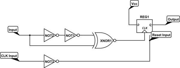
change xnor to xor
Source Link
Aaron
  • 8.5k
  • 1
  • 19
  • 35

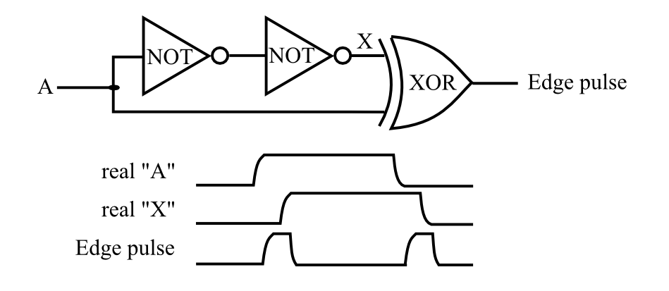
An edge detector like this should do the trick: dual edge detector

enter image description here

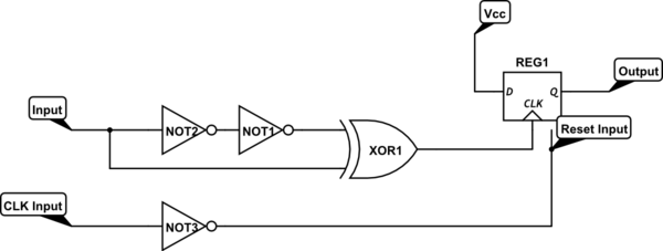
If the output falling edge needs to be synchronized with the rising edge of the clock, then feed the pulse output into the clock input of a D-Flop and the input clock to the reset input of the D-Flop. D input is tied high. The example circuit assumes the D-Flop uses low for reset. If high for reset type, then NOT3 gate can be removed.
schematicschematic

simulate this circuitsimulate this circuit – Schematic created using CircuitLab

An edge detector like this should do the trick: dual edge detector

enter image description here

If the output falling edge needs to be synchronized with the rising edge of the clock, then feed the pulse output into the clock input of a D-Flop and the input clock to the reset input of the D-Flop. D input is tied high. The example circuit assumes the D-Flop uses low for reset. If high for reset type, then NOT3 gate can be removed.

schematic

simulate this circuit – Schematic created using CircuitLab

added 227 characters in body
Source Link
Aaron
  • 8.5k
  • 1
  • 19
  • 35

An edge detector like this should do the trick: dual edge detector

enter image description here

If the output falling edge needs to be synchronized with the rising edge of the clock, then feed the pulse output into the clock input of a D-Flop and the input clock to the reset input of the D-Flop. D input is tied high. The example circuit assumes the D-Flop uses low for reset. If high for reset type, then NOT3 gate can be removed.

schematic

simulate this circuit – Schematic created using CircuitLab

An edge detector like this should do the trick: dual edge detector

enter image description here

If the output falling edge needs to be synchronized with the rising edge of the clock, then feed the pulse output into the clock input of a D-Flop and the input clock to the reset input of the D-Flop. D input is tied high.

An edge detector like this should do the trick: dual edge detector

enter image description here

If the output falling edge needs to be synchronized with the rising edge of the clock, then feed the pulse output into the clock input of a D-Flop and the input clock to the reset input of the D-Flop. D input is tied high. The example circuit assumes the D-Flop uses low for reset. If high for reset type, then NOT3 gate can be removed.

schematic

simulate this circuit – Schematic created using CircuitLab

added 227 characters in body
Source Link
Aaron
  • 8.5k
  • 1
  • 19
  • 35

An edge detector like this should do the trick: dual edge detector

enter image description here

If the output falling edge needs to be synchronized with the rising edge of the clock, then feed the pulse output into the clock input of a D-Flop and the input clock to the reset input of the D-Flop. D input is tied high.

An edge detector like this should do the trick: dual edge detector

enter image description here

An edge detector like this should do the trick: dual edge detector

enter image description here

If the output falling edge needs to be synchronized with the rising edge of the clock, then feed the pulse output into the clock input of a D-Flop and the input clock to the reset input of the D-Flop. D input is tied high.

Source Link
Aaron
  • 8.5k
  • 1
  • 19
  • 35
Loading