Additional informations added
Source Link

I am not an electrical engineer. I am a mechanical engineer and trying to improve myself in electronics. So, if there is a silly question please forgive me :)

I am developing a 24V BLDC motor controller, which adjusts the motor speed via PWM that comes from another circuit. However, this PWM is 16-32V. I have to lower this voltage to 5V to read via my STM8A MCU. The PWM frequency is 100Hz.

My main goal is;

  • Convert this PWM to 5V
  • Invert the PWM to read LOW side as HIGH (I know we can solve it by software, but I would like to do it using hardware)
  • MCU pulls (Edit: pulls to GND) the PWM line to send feedback (e.g. 1sec Gnd means overvoltage overvoltage)

I saw a circuit online and made my own. (You can see it below.) But, I couldn't understand it completely.

  • Why there is a 24V DC and R2 in this circuit?
  • How can I know the PWM current?
  • Do you think there is a problem with the circuit?

In LTspice, I am able to invert the PWM and lower the voltage, but could not send the feedback signal. Do you think there is a problem with the circuit?
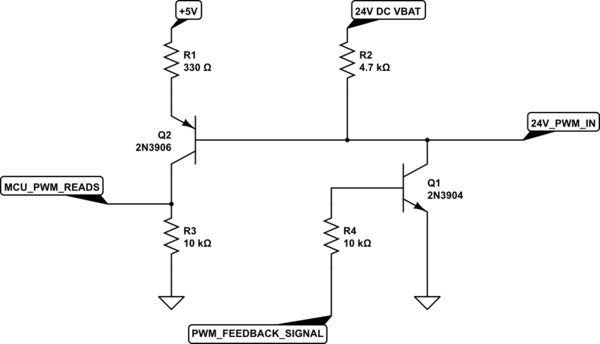
schematic

simulate this circuit – Schematic created using CircuitLab

##Edit Insufficient information created misunderstanding. So, I'll try to give more detail.

My BLDC controller is for trucks. There are only 3 inputs for this controller. 24V (Truck battery voltage), GND and PWM. The controller consist of a MCU, gate driver, and h-bridge. There is a 5V regulator for MCU. PWM voltage is the same voltage as VBAT. It is typically 24V but I wrote the range of it. So, we can consider it as 24V.

My circuit should send some feedbacks to the ECU. Because there is only 1 pin for communication, I send the feedbacks by pulling the PWM line to GND. As you understand from the circuit, PWM should be 5V also my feedback is 5V. There are 6 error feedbacks and I can read all of them. They all have a specific time to be GND. For example, if the motor is stuck I pull the PWM to GND for 4sec, if there is overcurrent I pull PWM to GND for 1sec. So, my question is not about overvoltage protection or reading circuit, just sending feedback.

I have no information about the source impedance or PWM generator.

Also, the maximum working temperature for this circuit is 140°C. So, it is hard to find an optocoupler for these temperatures.

I am not an electrical engineer. I am a mechanical engineer and trying to improve myself in electronics. So, if there is a silly question please forgive me :)

I am developing a 24V BLDC motor controller, which adjusts the motor speed via PWM that comes from another circuit. However, this PWM is 16-32V. I have to lower this voltage to 5V to read via my STM8A MCU. The PWM frequency is 100Hz.

My main goal is;

  • Convert this PWM to 5V
  • Invert the PWM to read LOW side as HIGH (I know we can solve it by software, but I would like to do it using hardware)
  • MCU pulls the PWM line to send feedback (e.g. 1sec Gnd means overvoltage)

I saw a circuit online and made my own. (You can see it below.) But, I couldn't understand it completely.

  • Why there is a 24V DC and R2 in this circuit?
  • How can I know the PWM current?

In LTspice, I am able to invert the PWM and lower the voltage, but could not send the feedback signal. Do you think there is a problem with the circuit?

schematic

simulate this circuit – Schematic created using CircuitLab

I am not an electrical engineer. I am a mechanical engineer and trying to improve myself in electronics. So, if there is a silly question please forgive me :)

I am developing a 24V BLDC motor controller, which adjusts the motor speed via PWM that comes from another circuit. However, this PWM is 16-32V. I have to lower this voltage to 5V to read via my STM8A MCU. The PWM frequency is 100Hz.

My main goal is;

  • Convert this PWM to 5V
  • Invert the PWM to read LOW side as HIGH (I know we can solve it by software, but I would like to do it using hardware)
  • MCU pulls (Edit: pulls to GND) the PWM line to send feedback (e.g. 1sec Gnd means overvoltage)

I saw a circuit online and made my own. (You can see it below.) But, I couldn't understand it completely.

  • Why there is a 24V DC and R2 in this circuit?
  • How can I know the PWM current?
  • Do you think there is a problem with the circuit?

schematic

simulate this circuit – Schematic created using CircuitLab

##Edit Insufficient information created misunderstanding. So, I'll try to give more detail.

My BLDC controller is for trucks. There are only 3 inputs for this controller. 24V (Truck battery voltage), GND and PWM. The controller consist of a MCU, gate driver, and h-bridge. There is a 5V regulator for MCU. PWM voltage is the same voltage as VBAT. It is typically 24V but I wrote the range of it. So, we can consider it as 24V.

My circuit should send some feedbacks to the ECU. Because there is only 1 pin for communication, I send the feedbacks by pulling the PWM line to GND. As you understand from the circuit, PWM should be 5V also my feedback is 5V. There are 6 error feedbacks and I can read all of them. They all have a specific time to be GND. For example, if the motor is stuck I pull the PWM to GND for 4sec, if there is overcurrent I pull PWM to GND for 1sec. So, my question is not about overvoltage protection or reading circuit, just sending feedback.

I have no information about the source impedance or PWM generator.

Also, the maximum working temperature for this circuit is 140°C. So, it is hard to find an optocoupler for these temperatures.

Removed signature per site rules: https://electronics.stackexchange.com/help/behavior | While I'm here, made small grammar changes to help readability.
Source Link
SamGibson
  • 18.3k
  • 5
  • 41
  • 63

I am not an electrical engineer. I am a mechanical engineer and trying to improve myself in electronics. So, if there is a silly question please forgive me :)

I am developing a 24V BLDC motor controller, which adjusts the motor speed via PWM that comes from another circuit. However, this PWM is 16-32V. I have to lower this voltage to 5V to read via my STM8A MCU. The PWM frequency is 100hz100Hz.

My main goal is;

  • Convert this PVMPWM to 5V
  • Invert the PWM to read LOW side as HIGH (I know we can solve it by software, but I would like to do it byusing hardware way)
  • MCU pulls the PWM line to send feedbacksfeedback (e.g. 1sec gndGnd means overvoltage)

I saw a circuit online and makemade my own. (You can see it below.) But, I couldn't understand it completely.

Why there is a 24V DC and R2 at this circuit?

How can I know the PWM current?

  • Why there is a 24V DC and R2 in this circuit?
  • How can I know the PWM current?

In LTspice, I am able to invert the PWM and lower the voltage, but could not send the feedback signal. Do you think there is a problem with the circuit?

schematic

simulate this circuit – Schematic created using CircuitLab

Thanks in advance,

Hilti_

I am not an electrical engineer. I am a mechanical engineer and trying to improve myself in electronics. So, if there is a silly question please forgive me :)

I am developing a 24V BLDC motor controller which adjusts the motor speed via PWM that comes from another circuit. However, this PWM is 16-32V I have to lower this voltage to 5V to read via my STM8A MCU. The PWM frequency is 100hz.

My main goal is;

  • Convert this PVM to 5V
  • Invert the PWM to read LOW side as HIGH (I know we can solve it by software but I would like to do it by hardware way)
  • MCU pulls the PWM line to send feedbacks (e.g. 1sec gnd means overvoltage)

I saw a circuit online and make my own. (You can see it below.) But, I couldn't understand it completely.

Why there is a 24V DC and R2 at this circuit?

How can I know the PWM current?

In LTspice, I am able to invert the PWM and lower the voltage but could not send the feedback signal. Do you think there is a problem with the circuit?

schematic

simulate this circuit – Schematic created using CircuitLab

Thanks in advance,

Hilti_

I am not an electrical engineer. I am a mechanical engineer and trying to improve myself in electronics. So, if there is a silly question please forgive me :)

I am developing a 24V BLDC motor controller, which adjusts the motor speed via PWM that comes from another circuit. However, this PWM is 16-32V. I have to lower this voltage to 5V to read via my STM8A MCU. The PWM frequency is 100Hz.

My main goal is;

  • Convert this PWM to 5V
  • Invert the PWM to read LOW side as HIGH (I know we can solve it by software, but I would like to do it using hardware)
  • MCU pulls the PWM line to send feedback (e.g. 1sec Gnd means overvoltage)

I saw a circuit online and made my own. (You can see it below.) But, I couldn't understand it completely.

  • Why there is a 24V DC and R2 in this circuit?
  • How can I know the PWM current?

In LTspice, I am able to invert the PWM and lower the voltage, but could not send the feedback signal. Do you think there is a problem with the circuit?

schematic

simulate this circuit – Schematic created using CircuitLab

Source Link

24V PWM to 5V inverted PWM

I am not an electrical engineer. I am a mechanical engineer and trying to improve myself in electronics. So, if there is a silly question please forgive me :)

I am developing a 24V BLDC motor controller which adjusts the motor speed via PWM that comes from another circuit. However, this PWM is 16-32V I have to lower this voltage to 5V to read via my STM8A MCU. The PWM frequency is 100hz.

My main goal is;

  • Convert this PVM to 5V
  • Invert the PWM to read LOW side as HIGH (I know we can solve it by software but I would like to do it by hardware way)
  • MCU pulls the PWM line to send feedbacks (e.g. 1sec gnd means overvoltage)

I saw a circuit online and make my own. (You can see it below.) But, I couldn't understand it completely.

Why there is a 24V DC and R2 at this circuit?

How can I know the PWM current?

In LTspice, I am able to invert the PWM and lower the voltage but could not send the feedback signal. Do you think there is a problem with the circuit?

schematic

simulate this circuit – Schematic created using CircuitLab

Thanks in advance,

Hilti_