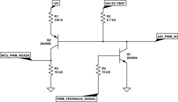
I am not an electrical engineer. I am a mechanical engineer and trying to improve myself in electronics. So, if there is a silly question please forgive me :)
I am developing a 24V BLDC motor controller, which adjusts the motor speed via PWM that comes from another circuit. However, this PWM is 16-32V. I have to lower this voltage to 5V to read via my STM8A MCU. The PWM frequency is 100Hz.
My main goal is;
- Convert this PWM to 5V
- Invert the PWM to read LOW side as HIGH (I know we can solve it by software, but I would like to do it using hardware)
- MCU pulls the PWM line to send feedback (e.g. 1sec Gnd means overvoltage)
I saw a circuit online and made my own. (You can see it below.) But, I couldn't understand it completely.
- Why there is a 24V DC and R2 in this circuit?
- How can I know the PWM current?
In LTspice, I am able to invert the PWM and lower the voltage, but could not send the feedback signal. Do you think there is a problem with the circuit?

simulate this circuit – Schematic created using CircuitLab
