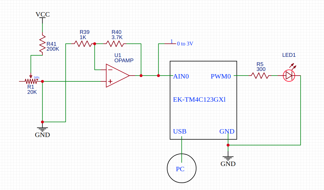
I'm doing a project in which I want to turn on an LED with different instensity depending on the input of a sensor. For now, I'm simulating the sensor with a potentiometer.
I'm using an EK-TM4C123GXl launchpad. I connect the 'fake' sensor input to an ADC input (through an op. amp.), then I vary the PWM pulse width depending on the value read from ADC.
I have tested that the PWM output powers the LED and varies its lightness depending on the current pulse width, having the ADC input is disconnected. However, as soon as I connect the ADC input, the PWM output goes to 0V (just after generating a 'spike' in the LED, I can see it because it brights a lot for an instant).
I have 'solved' the problem by placing a resistor between the PWM output and the LED. However, I don't understand at all why this happens. I have though that the PWM pulse is finding a way to ground through the MCU internals and the ADC input, I still don't see how can a resistor (R5) fix that.
The schematics is below (VCC is a 9V battery):
EDIT
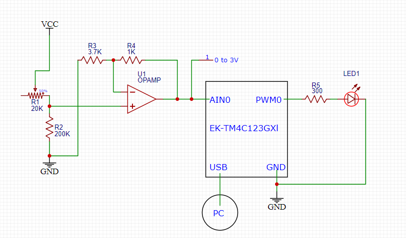
Previous schematics was wrong, here is the correct one:

The resistor R5 is the one that prevents the PWM output to go ground, that is, if I remove it and connect the LED directly to PWM0 it remains off and its anode at 0V.
How can this be happening? Can this be related with the input leakage current?
Pins configuration:
- ADC input pin: input, analog, no pull down resistor.
- PWM output pin: output, digital, no pull/down resistor, no open drain, 2mA drive strength.
Notes:
- VCC is a 9V battery
- I use a potentiometer and an op. amp. because the potentiometer is supposed to fake what will be an actual light sensor. The op. amp. is there for the shake of making the simulation more realistic, since I pretend to use it in the final design.
- I have tested that the op. amp. output is between 0 and ~3V (never more than 3)
- I connect the board GND pins to the same ground as all the other ICs.
- The MCU is powered by the USB port, which is connected to my PC.
- I don't provide the code because it's very long and I have tested several times that it's correct (I insist, everything works fine if R5 is present)
- All impedances are given in ohms.
- The op. amp. is non-inverting output (I remark this just in case I have made a mistake with it)
- I have read that the LED should always by protected by a current-limiting resistor. I didn't put it in first place because I misunderstood what the pin's drive strength is, but the point is I want to know how can the absence of R5 can cause PWM0 to go to 0V.

