Minor edit
Source Link
Circuit fantasist
  • 19.5k
  • 2
  • 24
  • 71

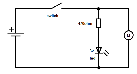
If you want a function to run Motor and LedLED after switch is ON your schematic is incorrect. Should be similar to this (exact resistor value depends on battery voltage and led type):

enter image description here

Function of switch is to disconnect the power supply from load (M an Ledand LED), another words break the current path (stop feeding them). Switch in your diagram does not break this path completelly because is not connected in series with both loads.

If you want a function to run Motor and Led after switch is ON your schematic is incorrect. Should be similar to this (exact resistor value depends on battery voltage and led type):

enter image description here

Function of switch is to disconnect the power supply from load (M an Led), another words break the current path (stop feeding them). Switch in your diagram does not break this path completelly because is not connected in series with both loads.

If you want a function to run Motor and LED after switch is ON your schematic is incorrect. Should be similar to this (exact resistor value depends on battery voltage and led type):

enter image description here

Function of switch is to disconnect the power supply from load (M and LED), another words break the current path (stop feeding them). Switch in your diagram does not break this path completelly because is not connected in series with both loads.

added 16 characters in body
Source Link
user208862
user208862

If you want a function to run Motor and Led after switch is ON your schematic is incorrect. Should be similar to this (exact resistor value depends on battery voltage and led type):

enter image description here

Function of switch is to disconnect the power supply from load (M an Led), another words break the current path (stop feeding them). Switch in your diagram does not break this path completelly because is not connected in series with both loads.

If you want a function to run Motor and Led after switch is ON your schematic is incorrect. Should be similar to this (exact resistor value depends on battery voltage and led type):

enter image description here

Function of switch is to disconnect the power supply from load (M an Led), another words break the current path. Switch in your diagram does not break this path because is not connected in series with loads.

If you want a function to run Motor and Led after switch is ON your schematic is incorrect. Should be similar to this (exact resistor value depends on battery voltage and led type):

enter image description here

Function of switch is to disconnect the power supply from load (M an Led), another words break the current path (stop feeding them). Switch in your diagram does not break this path completelly because is not connected in series with both loads.

Source Link
user208862
user208862

If you want a function to run Motor and Led after switch is ON your schematic is incorrect. Should be similar to this (exact resistor value depends on battery voltage and led type):

enter image description here

Function of switch is to disconnect the power supply from load (M an Led), another words break the current path. Switch in your diagram does not break this path because is not connected in series with loads.