added 461 characters in body
Source Link

Here is a circuit- enter image description here

It has 2 parts, the first part generates a triangular waveform with pk-pk voltage of \$1.2V\$ approx. The second part is a CE amplifier with intended circuit gain of \$-10\$. The problem is that the simulation doesn't comply with my calculations. Here are my calculations-

a) Considering \$I_{c}=1mA\$ at the \$Q-point\$, \$V_{C}\$ for \$Q4\$ is set to \$4.5V(=0.5 V_{CC})\$.

b) This gives the value of \$R5\$ to be \$4.5k\Omega\$. I've used \$4.7k\$ due to availability issues, since I've to demonstrate this circuit as well.

c) This allows \$R6\$ to be around \$470\Omega\$, giving \$V_{E}\$ to be around \$0.5V\$.

d) \$V_{B}=1.2V\$ at the \$Q-point\$, thus.

Here are the detailed calculations-

a) Using resistors RC2/RC1 and the capacitors C12/C21, the time for charging the capacitors would be \$RC2*C21*ln(2)\$. This can be multiplied by 2, since values are the same, to get the time period, and hence the frequency.

b)For Q3, input impedance is \$47k\Omega\$ when input is high, and \$\infty\$ when input is low.

c)The thevenin equivalent output impedance for Q3 would be around \$1k\Omega\$ itself.

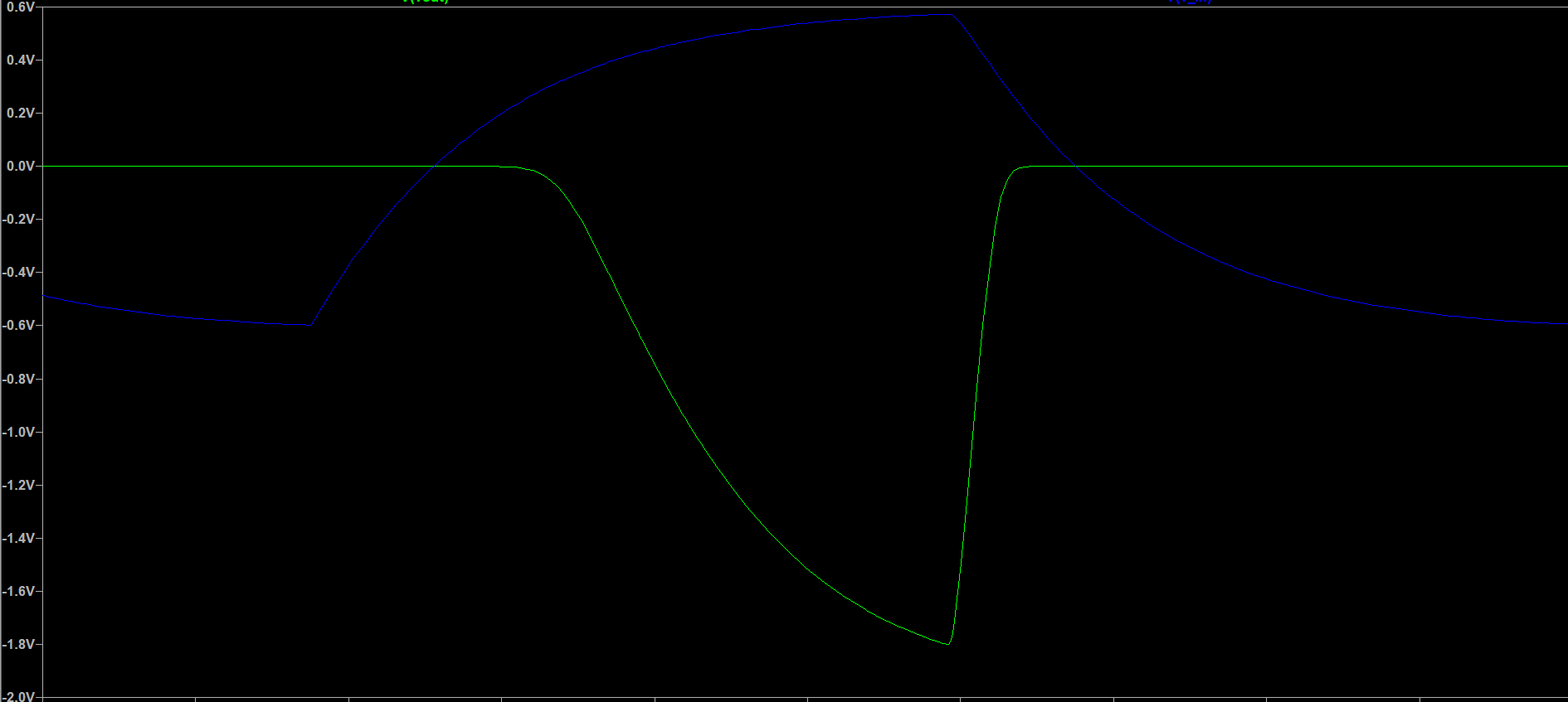
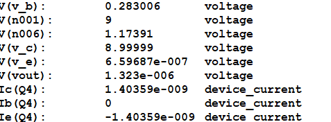
Using these, I expect a gain of -10 (opposite phase due to the negative sign), and thus around -6V. But, according to the simulation, I only get get around -1.8V(a gain of around -3). Also, the quiescent values of \$Q4\$'s terminals do not match according to my calculations, nor does the quiescent collector current. enter image description here enter image description here
I don't realise where I'm going wrong horribly. Am I somehow neglecting the internal emitter resistance as seen by the base (\$=\beta r_{e}\$)? Should it be incorporated in the circuit gain? Can someone help me out in this?

Here is a circuit- enter image description here

It has 2 parts, the first part generates a triangular waveform with pk-pk voltage of \$1.2V\$ approx. The second part is a CE amplifier with intended circuit gain of \$-10\$. The problem is that the simulation doesn't comply with my calculations. Here are my calculations-

a) Considering \$I_{c}=1mA\$ at the \$Q-point\$, \$V_{C}\$ for \$Q4\$ is set to \$4.5V(=0.5 V_{CC})\$.

b) This gives the value of \$R5\$ to be \$4.5k\Omega\$. I've used \$4.7k\$ due to availability issues, since I've to demonstrate this circuit as well.

c) This allows \$R6\$ to be around \$470\Omega\$, giving \$V_{E}\$ to be around \$0.5V\$.

d) \$V_{B}=1.2V\$ at the \$Q-point\$, thus.

Using these, I expect a gain of -10 (opposite phase due to the negative sign), and thus around -6V. But, according to the simulation, I only get around -1.8V(a gain of around -3). Also, the quiescent values of \$Q4\$'s terminals do not match according to my calculations, nor does the quiescent collector current. enter image description here enter image description here
I don't realise where I'm going wrong horribly. Am I somehow neglecting the internal emitter resistance as seen by the base (\$=\beta r_{e}\$)? Should it be incorporated in the circuit gain? Can someone help me out in this?

Here is a circuit- enter image description here

It has 2 parts, the first part generates a triangular waveform with pk-pk voltage of \$1.2V\$ approx. The second part is a CE amplifier with intended circuit gain of \$-10\$. The problem is that the simulation doesn't comply with my calculations. Here are my calculations-

a) Considering \$I_{c}=1mA\$ at the \$Q-point\$, \$V_{C}\$ for \$Q4\$ is set to \$4.5V(=0.5 V_{CC})\$.

b) This gives the value of \$R5\$ to be \$4.5k\Omega\$. I've used \$4.7k\$ due to availability issues, since I've to demonstrate this circuit as well.

c) This allows \$R6\$ to be around \$470\Omega\$, giving \$V_{E}\$ to be around \$0.5V\$.

d) \$V_{B}=1.2V\$ at the \$Q-point\$, thus.

Here are the detailed calculations-

a) Using resistors RC2/RC1 and the capacitors C12/C21, the time for charging the capacitors would be \$RC2*C21*ln(2)\$. This can be multiplied by 2, since values are the same, to get the time period, and hence the frequency.

b)For Q3, input impedance is \$47k\Omega\$ when input is high, and \$\infty\$ when input is low.

c)The thevenin equivalent output impedance for Q3 would be around \$1k\Omega\$ itself.

Using these, I expect a gain of -10 (opposite phase due to the negative sign), and thus around -6V. But, according to the simulation, I only get around -1.8V(a gain of around -3). Also, the quiescent values of \$Q4\$'s terminals do not match according to my calculations, nor does the quiescent collector current. enter image description here enter image description here

I don't realise where I'm going wrong horribly. Am I somehow neglecting the internal emitter resistance as seen by the base (\$=\beta r_{e}\$)? Should it be incorporated in the circuit gain? Can someone help me out in this?

Source Link

Simulation on LTSpice not matching with Calculations at Q-point

Here is a circuit- enter image description here

It has 2 parts, the first part generates a triangular waveform with pk-pk voltage of \$1.2V\$ approx. The second part is a CE amplifier with intended circuit gain of \$-10\$. The problem is that the simulation doesn't comply with my calculations. Here are my calculations-

a) Considering \$I_{c}=1mA\$ at the \$Q-point\$, \$V_{C}\$ for \$Q4\$ is set to \$4.5V(=0.5 V_{CC})\$.

b) This gives the value of \$R5\$ to be \$4.5k\Omega\$. I've used \$4.7k\$ due to availability issues, since I've to demonstrate this circuit as well.

c) This allows \$R6\$ to be around \$470\Omega\$, giving \$V_{E}\$ to be around \$0.5V\$.

d) \$V_{B}=1.2V\$ at the \$Q-point\$, thus.

Using these, I expect a gain of -10 (opposite phase due to the negative sign), and thus around -6V. But, according to the simulation, I only get around -1.8V(a gain of around -3). Also, the quiescent values of \$Q4\$'s terminals do not match according to my calculations, nor does the quiescent collector current. enter image description here enter image description here

I don't realise where I'm going wrong horribly. Am I somehow neglecting the internal emitter resistance as seen by the base (\$=\beta r_{e}\$)? Should it be incorporated in the circuit gain? Can someone help me out in this?