added 247 characters in body
Source Link

I am trying to use this photogate with my Arduino Pro Mini (5V.) I am having no luck getting any readings from it.

I measured the voltage across the emitter and got 4.5V, which should be enough to power the LED so I think the issue might be on the receiver side. I have tried using an external power supply up to 12V to power the receiver with some more juice (no difference.) I have the output pin hooked up to a multimeter and am consistently getting 0.1mV. I've tried this same setup with a different photogate and had no issues.

Here's my code if it's helpful at all:

    const int sensIn =A0;
const int ledPin = 13;
const int green = 7;
int value;

void setup() { 
  Serial.begin(9600);
//  pinMode(red, OUTPUT);
  pinMode(green, OUTPUT);
  pinMode(sensIn, INPUT);
  pinMode(ledPin, OUTPUT);
}

void loop() {  
  digitalWrite(ledPin, HIGH);
  delayMicroseconds(500);
  value=analogRead(sensIn);
  Serial.println(value);
     delayMicroseconds(500);
  digitalWrite(ledPin, LOW);
  delayMicroseconds(500);
  if(value==0){
    digitalWrite(green, LOW);
  }
  else{
    digitalWrite(green, HIGH);
  }
}

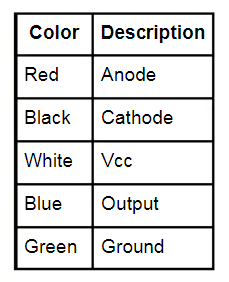
Here's a picture of the breadboard and what each wire is. The blue wire is on pin 12 because that's when I was trying to use a digital pin rather than the analog one from the code. Sorry for the inconsistency:

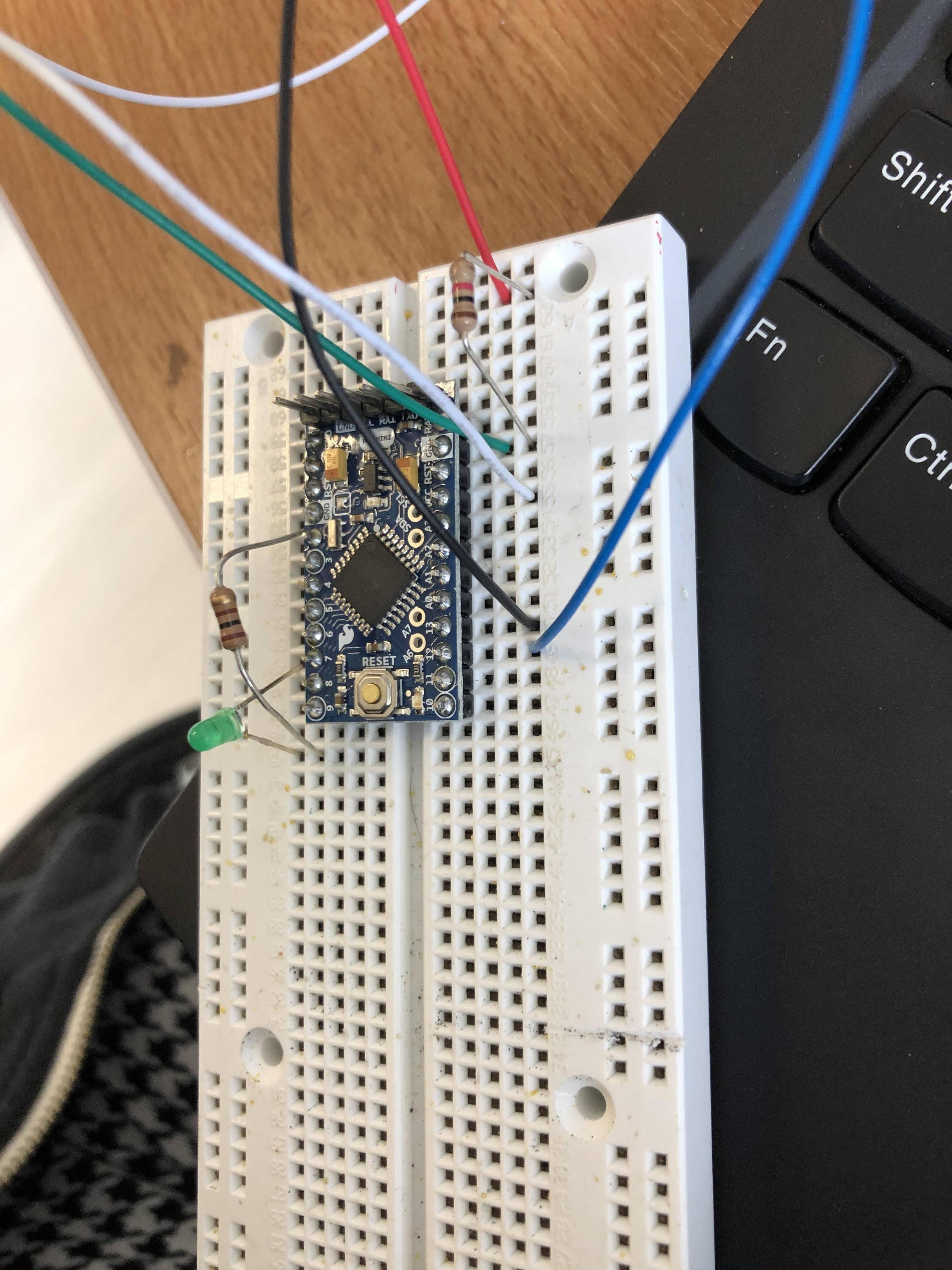
circuit

wire colors

I am trying to use this photogate with my Arduino Pro Mini (5V.) I am having no luck getting any readings from it.

I measured the voltage across the emitter and got 4.5V, which should be enough to power the LED so I think the issue might be on the receiver side. I have tried using an external power supply up to 12V to power the receiver with some more juice (no difference.) I have the output pin hooked up to a multimeter and am consistently getting 0.1mV. I've tried this same setup with a different photogate and had no issues.

Here's my code if it's helpful at all:

    const int sensIn =A0;
const int ledPin = 13;
const int green = 7;
int value;

void setup() { 
  Serial.begin(9600);
//  pinMode(red, OUTPUT);
  pinMode(green, OUTPUT);
  pinMode(sensIn, INPUT);
  pinMode(ledPin, OUTPUT);
}

void loop() {  
  digitalWrite(ledPin, HIGH);
  delayMicroseconds(500);
  value=analogRead(sensIn);
  Serial.println(value);
     delayMicroseconds(500);
  digitalWrite(ledPin, LOW);
  delayMicroseconds(500);
  if(value==0){
    digitalWrite(green, LOW);
  }
  else{
    digitalWrite(green, HIGH);
  }
}

Here's a picture of the breadboard:

circuit

I am trying to use this photogate with my Arduino Pro Mini (5V.) I am having no luck getting any readings from it.

I measured the voltage across the emitter and got 4.5V, which should be enough to power the LED so I think the issue might be on the receiver side. I have tried using an external power supply up to 12V to power the receiver with some more juice (no difference.) I have the output pin hooked up to a multimeter and am consistently getting 0.1mV. I've tried this same setup with a different photogate and had no issues.

Here's my code if it's helpful at all:

    const int sensIn =A0;
const int ledPin = 13;
const int green = 7;
int value;

void setup() { 
  Serial.begin(9600);
//  pinMode(red, OUTPUT);
  pinMode(green, OUTPUT);
  pinMode(sensIn, INPUT);
  pinMode(ledPin, OUTPUT);
}

void loop() {  
  digitalWrite(ledPin, HIGH);
  delayMicroseconds(500);
  value=analogRead(sensIn);
  Serial.println(value);
     delayMicroseconds(500);
  digitalWrite(ledPin, LOW);
  delayMicroseconds(500);
  if(value==0){
    digitalWrite(green, LOW);
  }
  else{
    digitalWrite(green, HIGH);
  }
}

Here's a picture of the breadboard and what each wire is. The blue wire is on pin 12 because that's when I was trying to use a digital pin rather than the analog one from the code. Sorry for the inconsistency:
circuit

wire colors

added 12 characters in body
Source Link
JRE
  • 73.6k
  • 10
  • 112
  • 195

Hi I am trying to use this https://www.digikey.com/en/htmldatasheets/production/101867/0/0/1/opb917iz.html?site=US&lang=en&cur=USDthis photogate photogate with my Arduino pro miniPro Mini (5V.) andI am having no luck getting any readings from it. 

I measured the voltage across the emitter and got 4.5V, which should be enough to power the LED so I think the issue might be on the receiver side. I have tried using an external power supply up to 12V to power the receiver with some more juice (no difference).) I have the output pin hooked up to a multimeter and am consistently getting 0.1mV. I've tried this same setup with a different photogate (https://www.sparkfun.com/datasheets/Components/GP1A57HRJ00F.pdfdifferent photogate) and had no issues.

Here's my code if it's helpful at all:

    const int sensIn =A0;
const int ledPin = 13;
const int green = 7;
int value;

void setup() { 
  Serial.begin(9600);
//  pinMode(red, OUTPUT);
  pinMode(green, OUTPUT);
  pinMode(sensIn, INPUT);
  pinMode(ledPin, OUTPUT);
}

void loop() {  
  digitalWrite(ledPin, HIGH);
  delayMicroseconds(500);
  value=analogRead(sensIn);
  Serial.println(value);
     delayMicroseconds(500);
  digitalWrite(ledPin, LOW);
  delayMicroseconds(500);
  if(value==0){
    digitalWrite(green, LOW);
  }
  else{
    digitalWrite(green, HIGH);
  }
}

Here's a picture of the breadboard  :

circuit

Hi I am trying to use this https://www.digikey.com/en/htmldatasheets/production/101867/0/0/1/opb917iz.html?site=US&lang=en&cur=USD photogate with my Arduino pro mini (5V) and am having no luck getting any readings from it. I measured the voltage across the emitter and got 4.5V, which should be enough to power the LED so I think the issue might be on the receiver side. I have tried using an external power supply up to 12V to power the receiver with some more juice (no difference). I have the output pin hooked up to a multimeter and am consistently getting 0.1mV. I've tried this same setup with a different photogate (https://www.sparkfun.com/datasheets/Components/GP1A57HRJ00F.pdf) and had no issues.

Here's my code if it's helpful at all

    const int sensIn =A0;
const int ledPin = 13;
const int green = 7;
int value;

void setup() { 
  Serial.begin(9600);
//  pinMode(red, OUTPUT);
  pinMode(green, OUTPUT);
  pinMode(sensIn, INPUT);
  pinMode(ledPin, OUTPUT);
}

void loop() {  
  digitalWrite(ledPin, HIGH);
  delayMicroseconds(500);
  value=analogRead(sensIn);
  Serial.println(value);
     delayMicroseconds(500);
  digitalWrite(ledPin, LOW);
  delayMicroseconds(500);
  if(value==0){
    digitalWrite(green, LOW);
  }
  else{
    digitalWrite(green, HIGH);
  }
}

Here's a picture of the breadboard  circuit

I am trying to use this photogate with my Arduino Pro Mini (5V.) I am having no luck getting any readings from it. 

I measured the voltage across the emitter and got 4.5V, which should be enough to power the LED so I think the issue might be on the receiver side. I have tried using an external power supply up to 12V to power the receiver with some more juice (no difference.) I have the output pin hooked up to a multimeter and am consistently getting 0.1mV. I've tried this same setup with a different photogate and had no issues.

Here's my code if it's helpful at all:

    const int sensIn =A0;
const int ledPin = 13;
const int green = 7;
int value;

void setup() { 
  Serial.begin(9600);
//  pinMode(red, OUTPUT);
  pinMode(green, OUTPUT);
  pinMode(sensIn, INPUT);
  pinMode(ledPin, OUTPUT);
}

void loop() {  
  digitalWrite(ledPin, HIGH);
  delayMicroseconds(500);
  value=analogRead(sensIn);
  Serial.println(value);
     delayMicroseconds(500);
  digitalWrite(ledPin, LOW);
  delayMicroseconds(500);
  if(value==0){
    digitalWrite(green, LOW);
  }
  else{
    digitalWrite(green, HIGH);
  }
}

Here's a picture of the breadboard:

circuit

edited body
Source Link

Hi I am trying to use this https://www.digikey.com/en/htmldatasheets/production/101867/0/0/1/opb917iz.html?site=US&lang=en&cur=USD photogate with my Arduino pro mini (5V) and am having no luck getting any readings from it. I measured the voltage across the emitter and got 4.5V, which should be enough to power the LED so I think the issue might be on the receiver side. I have tried using an external power supply up to 12V to power the receiver with some more juice (no difference). I have the output pin hooked up to a multimeter and am consistently getting 0.1mA1mV. I've tried this same setup with a different photogate (https://www.sparkfun.com/datasheets/Components/GP1A57HRJ00F.pdf) and had no issues.

Here's my code if it's helpful at all

    const int sensIn =A0;
const int ledPin = 13;
const int green = 7;
int value;

void setup() { 
  Serial.begin(9600);
//  pinMode(red, OUTPUT);
  pinMode(green, OUTPUT);
  pinMode(sensIn, INPUT);
  pinMode(ledPin, OUTPUT);
}

void loop() {  
  digitalWrite(ledPin, HIGH);
  delayMicroseconds(500);
  value=analogRead(sensIn);
  Serial.println(value);
     delayMicroseconds(500);
  digitalWrite(ledPin, LOW);
  delayMicroseconds(500);
  if(value==0){
    digitalWrite(green, LOW);
  }
  else{
    digitalWrite(green, HIGH);
  }
}

Here's a picture of the breadboard circuit

Hi I am trying to use this https://www.digikey.com/en/htmldatasheets/production/101867/0/0/1/opb917iz.html?site=US&lang=en&cur=USD photogate with my Arduino pro mini (5V) and am having no luck getting any readings from it. I measured the voltage across the emitter and got 4.5V, which should be enough to power the LED so I think the issue might be on the receiver side. I have tried using an external power supply up to 12V to power the receiver with some more juice (no difference). I have the output pin hooked up to a multimeter and am consistently getting 0.1mA. I've tried this same setup with a different photogate (https://www.sparkfun.com/datasheets/Components/GP1A57HRJ00F.pdf) and had no issues.

Here's my code if it's helpful at all

    const int sensIn =A0;
const int ledPin = 13;
const int green = 7;
int value;

void setup() { 
  Serial.begin(9600);
//  pinMode(red, OUTPUT);
  pinMode(green, OUTPUT);
  pinMode(sensIn, INPUT);
  pinMode(ledPin, OUTPUT);
}

void loop() {  
  digitalWrite(ledPin, HIGH);
  delayMicroseconds(500);
  value=analogRead(sensIn);
  Serial.println(value);
     delayMicroseconds(500);
  digitalWrite(ledPin, LOW);
  delayMicroseconds(500);
  if(value==0){
    digitalWrite(green, LOW);
  }
  else{
    digitalWrite(green, HIGH);
  }
}

Here's a picture of the breadboard circuit

Hi I am trying to use this https://www.digikey.com/en/htmldatasheets/production/101867/0/0/1/opb917iz.html?site=US&lang=en&cur=USD photogate with my Arduino pro mini (5V) and am having no luck getting any readings from it. I measured the voltage across the emitter and got 4.5V, which should be enough to power the LED so I think the issue might be on the receiver side. I have tried using an external power supply up to 12V to power the receiver with some more juice (no difference). I have the output pin hooked up to a multimeter and am consistently getting 0.1mV. I've tried this same setup with a different photogate (https://www.sparkfun.com/datasheets/Components/GP1A57HRJ00F.pdf) and had no issues.

Here's my code if it's helpful at all

    const int sensIn =A0;
const int ledPin = 13;
const int green = 7;
int value;

void setup() { 
  Serial.begin(9600);
//  pinMode(red, OUTPUT);
  pinMode(green, OUTPUT);
  pinMode(sensIn, INPUT);
  pinMode(ledPin, OUTPUT);
}

void loop() {  
  digitalWrite(ledPin, HIGH);
  delayMicroseconds(500);
  value=analogRead(sensIn);
  Serial.println(value);
     delayMicroseconds(500);
  digitalWrite(ledPin, LOW);
  delayMicroseconds(500);
  if(value==0){
    digitalWrite(green, LOW);
  }
  else{
    digitalWrite(green, HIGH);
  }
}

Here's a picture of the breadboard circuit

added 107 characters in body
Source Link
Loading
Source Link
Loading