0
\$\begingroup\$

I am trying to use this photogate with my Arduino Pro Mini (5V.) I am having no luck getting any readings from it.

I measured the voltage across the emitter and got 4.5V, which should be enough to power the LED so I think the issue might be on the receiver side. I have tried using an external power supply up to 12V to power the receiver with some more juice (no difference.) I have the output pin hooked up to a multimeter and am consistently getting 0.1mV. I've tried this same setup with a different photogate and had no issues.

Here's my code if it's helpful at all:

    const int sensIn =A0;
const int ledPin = 13;
const int green = 7;
int value;

void setup() { 
  Serial.begin(9600);
//  pinMode(red, OUTPUT);
  pinMode(green, OUTPUT);
  pinMode(sensIn, INPUT);
  pinMode(ledPin, OUTPUT);
}

void loop() {  
  digitalWrite(ledPin, HIGH);
  delayMicroseconds(500);
  value=analogRead(sensIn);
  Serial.println(value);
     delayMicroseconds(500);
  digitalWrite(ledPin, LOW);
  delayMicroseconds(500);
  if(value==0){
    digitalWrite(green, LOW);
  }
  else{
    digitalWrite(green, HIGH);
  }
}

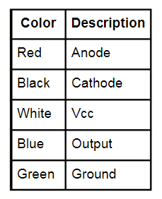
Here's a picture of the breadboard and what each wire is. The blue wire is on pin 12 because that's when I was trying to use a digital pin rather than the analog one from the code. Sorry for the inconsistency:

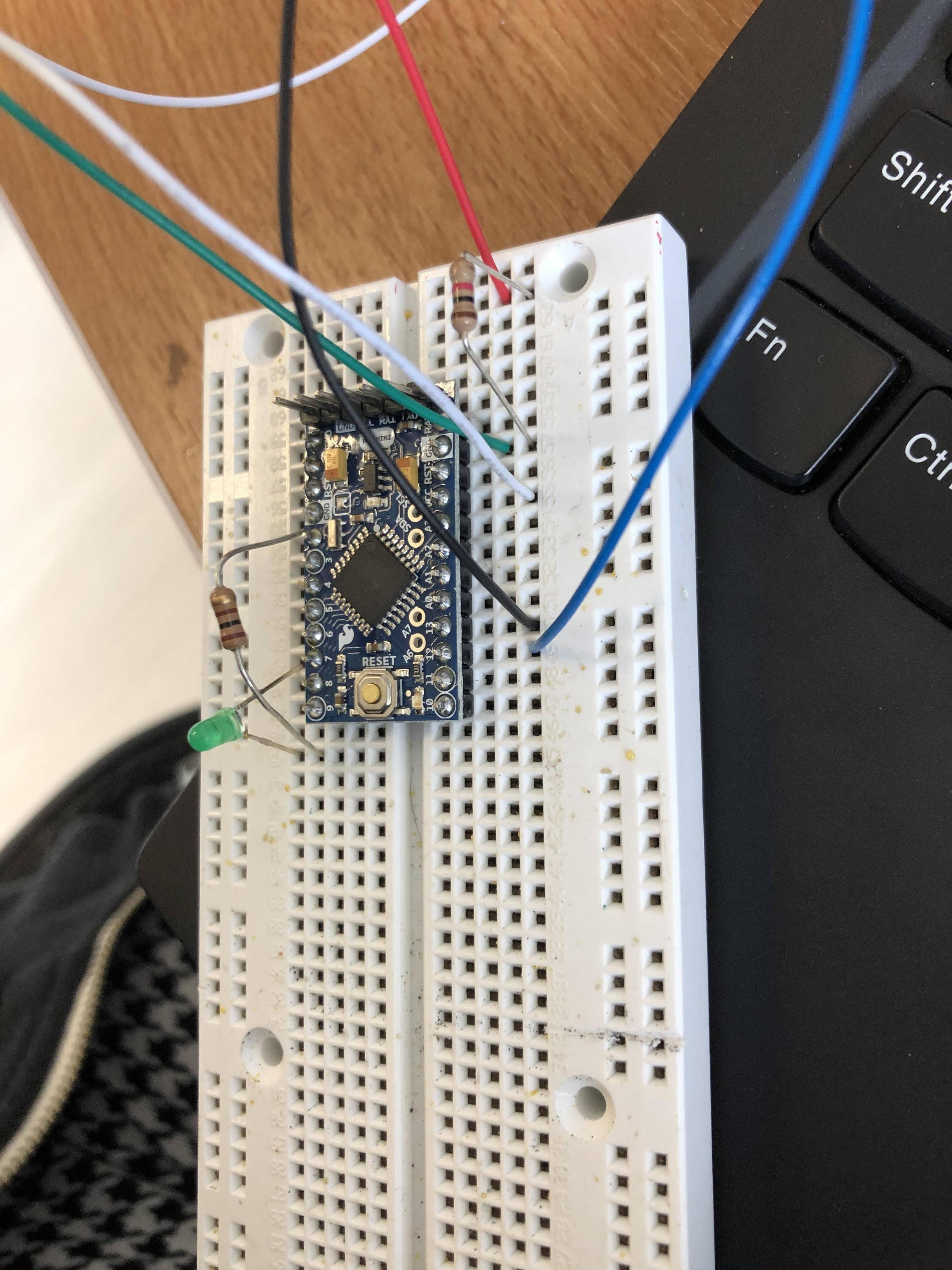
circuit

wire colors

\$\endgroup\$
3
  • \$\begingroup\$ Give us a diagram: how is this hooked up? You said you measured you voltage "across the emitter"; the emitter is a single point which is grounded in the sensor. Are you measuring from the emitter to the output? You say it's powering an LED but then talk about hooking it up to an Arduino. You have a TTL-compatible sensor but are reading it with an analog input? The VCE of the transistor will never be zero, so the output of the sensor will also never be zero so your threshold needs to be higher, or use a digitalRead for the signal. \$\endgroup\$
    – vir
    Commented Sep 8, 2021 at 17:15
  • \$\begingroup\$ I added a picture of the breadboard so you can see what I'm talking about. When I say measuring voltage across the emitter what I mean is the voltage difference between pin 13 and ground. Pin 13 is connected to the emitter side of the photogate, which is comprised of an IR LED. The other side should in theory be able to detect the presence or absence of the beam from that IR LED. I'm not quite sure what you mean by TTL. I have tried it as a digitalRead and got the same results. If I connect just the blue wire to the multimeter and measure the difference between there and ground I get 0.1mV \$\endgroup\$ Commented Sep 8, 2021 at 17:39
  • \$\begingroup\$ Please edit and add to the OP (not as a comment) what each of the colored wires is meant to be. \$\endgroup\$
    – Aaron
    Commented Sep 8, 2021 at 18:03

1 Answer 1

0
\$\begingroup\$

The red and black wires look like they are swapped and the blue wire should go to pin A0, not pin 13

\$\endgroup\$
1
  • \$\begingroup\$ Tried this, no luck \$\endgroup\$ Commented Sep 8, 2021 at 19:48

Your Answer

By clicking “Post Your Answer”, you agree to our terms of service and acknowledge you have read our privacy policy.

Not the answer you're looking for? Browse other questions tagged or ask your own question.