I have been experimenting with a ESP8266-01 module (8-Pinpin).
I would like to use the ESP-01 module as an MQTT client and control two relays. For
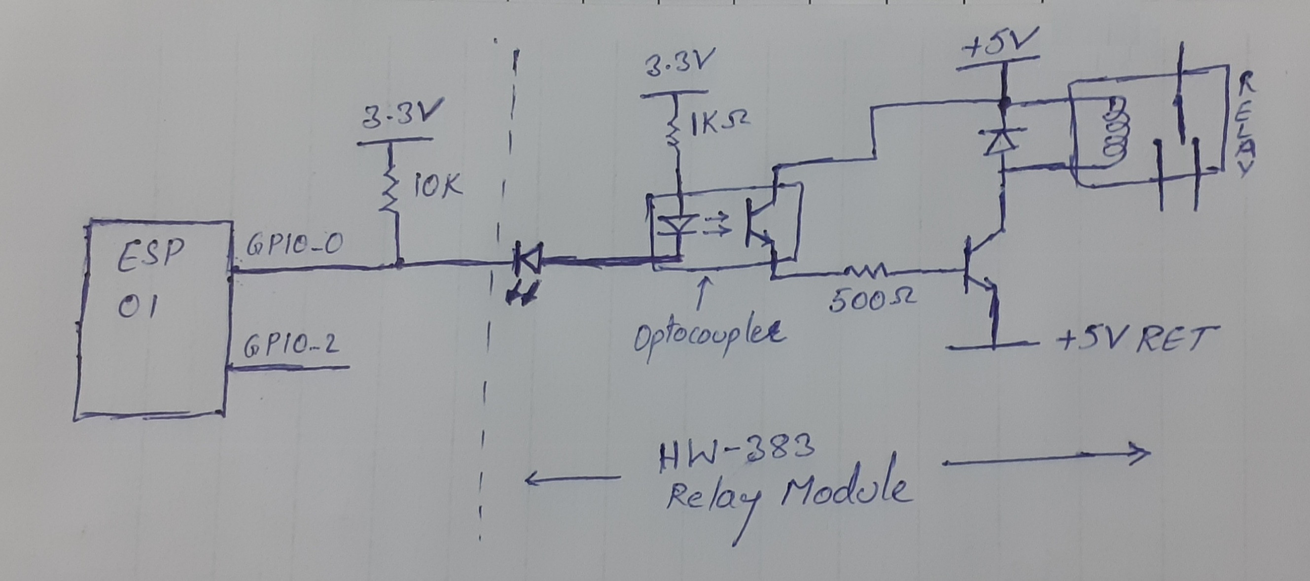
For this iI bought aan ESP-01 module and a 2-CH relay module (HW-383) and my schematic is as below (GPIO-2 also has the same circuit as GPIO-0GPIO-2 has the same circuit as GPIO-0):
The EPS-01 and the optocoupler share +3.3V3 V which is isolated from +5Vthe +5 V used for relay and transistor. I pulled GPIO-0 and GPIO-2 to 3.3V3 V using 10K10 kΩ as it is necessary for ESP to boot properly.
Everything is working perfectly except the flicker (relay turn ON and then OFF) during ESP-01 boot or reset. (Inin my code iI have set GPIOs asto HIGH and then set them as O/P).
I read that this is due to the internal process of the ESP module. FewA few people suggest to useusing GPIO-2 to avoid flicker and a few suggest to addadding a 470uF470 μF capacitor across the optocoupler input terminals (only few people hashad success with a capacitor).
Is it a good idea to add a capcapacitor across the optocoupler (OR)? Can iI add a capacitor across the GPIO pin and 3.3V_GND.3 V_GND? Both ways cause the capcapacitor to discharge into the GPIO pins at LOW signal on GPIO, is this safe for the ESP-01.? If so, what is the optimum value offor the capacitor.?
Or do iI need to add aan RC network between the GPIO and the optocoupler to delay the switch ON of optocoupler (schematic would be helpful).?
I know there are lots of discussions on this topic but iI could not find a reliable solution.
Update:
AHere's a link to detailed GPIO behavior during boot is below
https://bbs.espressif.com/viewtopic.php?t=2101#p6636detailed GPIO behavior
The during boot.
The last post in the form says "GPIO0 will output the clock frequency (e.g 26MHz26 MHz) of the external crystal by default".
I
I think this clock might be causing the relay to turn ON and OFF during boot. How to avoid relay turn ON during this clock output.How to avoid relay turn ON during this clock output?

