added 40 characters in body
Source Link

Your schematics looks good and it would work. But to turn off the LED current, you should give High to the NPN transistor's base. It will cause a leakage current when the LED is off. But if your design is not requiring low-power consumption, it will be not a serious issue.

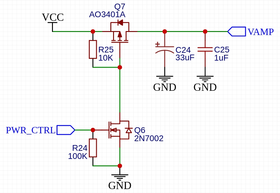
As a reference, here I attach similar power gate circuit from one of our reference design. It is tested and worked well on real PCBA prototypes.

The major difference with yours is that here P-Channel MOSFET is used to gate tehthe VCC line. Thus, the logic level is not reversed.

enter image description here

Your schematics looks good and it would work. But to turn off the LED current, you should give High to the NPN transistor's base. It will cause a leakage current when the LED is off. But if your design is not requiring low-power consumption, it will be not a serious issue.

As a reference, here I attach similar power gate circuit from one of our reference design. It is tested and worked well on real PCBA prototypes.

The major difference with yours is that here P-Channel MOSFET is used to gate teh VCC line.

enter image description here

Your schematics looks good and it would work. But to turn off the LED current, you should give High to the NPN transistor's base. It will cause a leakage current when the LED is off. But if your design is not requiring low-power consumption, it will be not a serious issue.

As a reference, here I attach similar power gate circuit from one of our reference design. It is tested and worked well on real PCBA prototypes.

The major difference with yours is that here P-Channel MOSFET is used to gate the VCC line. Thus, the logic level is not reversed.

enter image description here

Source Link

Your schematics looks good and it would work. But to turn off the LED current, you should give High to the NPN transistor's base. It will cause a leakage current when the LED is off. But if your design is not requiring low-power consumption, it will be not a serious issue.

As a reference, here I attach similar power gate circuit from one of our reference design. It is tested and worked well on real PCBA prototypes.

The major difference with yours is that here P-Channel MOSFET is used to gate teh VCC line.

enter image description here