0
\$\begingroup\$

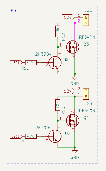
I want to control a 5A maximum 12V LED strip from a 3.3V ESP32.

I want do all of this with THT components ideally. I've been struggling to find the best way to drive the N FET so settled with an NPN as all of the IC drivers require 5V input.

Does the below schematic look like it should work or could anything be changed such as resistor values, possibly a gate drain resistor?

Mosfets

\$\endgroup\$
8
  • 1
    \$\begingroup\$ The upper side of R13 should be connected to 12V, not the low side of the LEDs. Otherwise this circuit will find an equilibrium, where the LEDs' negative voltage is still high enough to turn the gate on. \$\endgroup\$ Commented Mar 24, 2022 at 9:57
  • 1
    \$\begingroup\$ 470 ohms is probably smaller than necessary (but I didn't calculate it), wasting a little bit of power. \$\endgroup\$ Commented Mar 24, 2022 at 9:58
  • 1
    \$\begingroup\$ What you expect to gain by the BJT turn-off will be lost with the 10k pull-up turn-on. Get a MOSFET with low enough Vgsth to cope with 3.3 V gate drive. \$\endgroup\$
    – winny
    Commented Mar 24, 2022 at 10:25
  • \$\begingroup\$ @winny there are no readily available 3.3v fets capable of 5-10 amps continuous that arent SMD and I would much rather use a THT version for simple assembly \$\endgroup\$
    – robbrown92
    Commented Mar 25, 2022 at 10:08
  • 1
    \$\begingroup\$ The FQP30N60 datasheet shows maximum Vgs threshold voltage of 4V, exactly the same as the IRF540. It's possible that it might not turn on at all at 3.3V and highly likely that it won't turn on enough to safely carry 10A. \$\endgroup\$
    – Finbarr
    Commented Mar 25, 2022 at 11:04

2 Answers 2

4
\$\begingroup\$

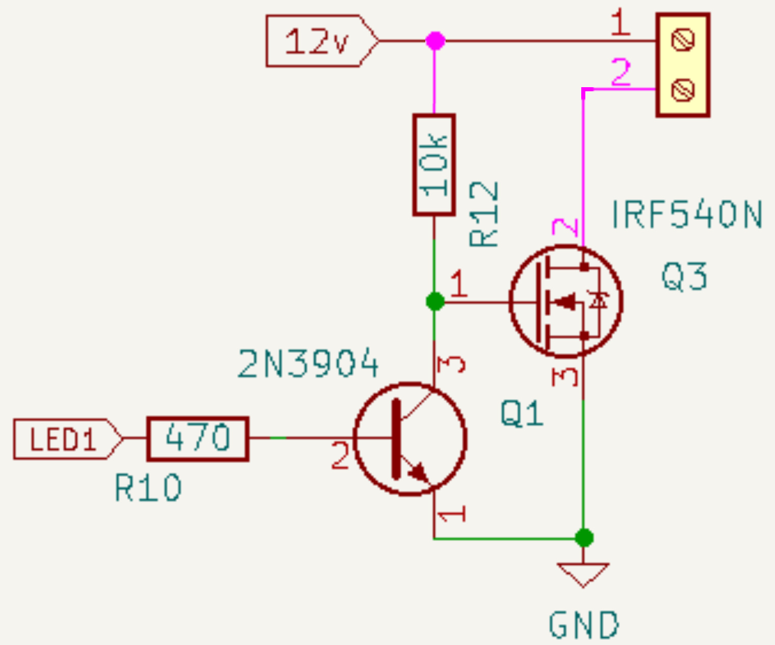
No. The problem is that when the MOSFET switches on, the voltage across it will fall down towards zero and that will reduce the supply to the resistor that drives the gate and turns it on. Instead of turning fully on it'll settle in a state where the drain-source voltage is somewhere around the Vgs threshold voltage for the device, dissipating a load of power and overheating.

Connect the pullup resistor directly to the 12V supply instead:

enter image description here

\$\endgroup\$
1
  • \$\begingroup\$ Good catch! Didn’t even see that since one would assume it’s pulled up to +12V. \$\endgroup\$
    – winny
    Commented Mar 24, 2022 at 16:10
0
\$\begingroup\$

Your schematics looks good and it would work. But to turn off the LED current, you should give High to the NPN transistor's base. It will cause a leakage current when the LED is off. But if your design is not requiring low-power consumption, it will be not a serious issue.

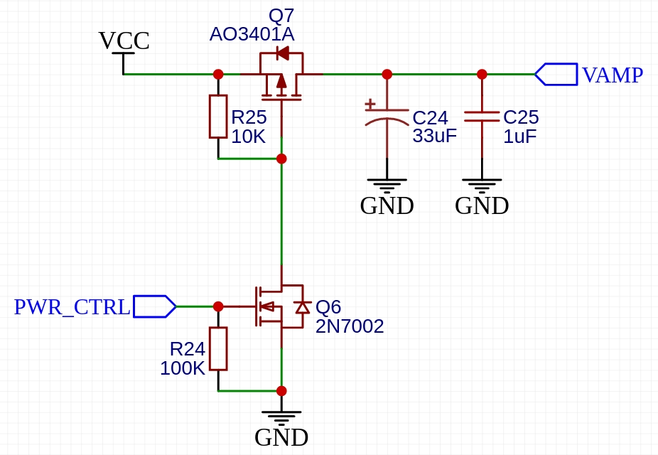
As a reference, here I attach similar power gate circuit from one of our reference design. It is tested and worked well on real PCBA prototypes.

The major difference with yours is that here P-Channel MOSFET is used to gate the VCC line. Thus, the logic level is not reversed.

enter image description here

\$\endgroup\$
1
  • \$\begingroup\$ Power consumption isn’t a huge issue though I would prefer the led to be off when the signal from the esp is low, so that if it is powered off or rebooting the light is off. \$\endgroup\$
    – robbrown92
    Commented Mar 23, 2022 at 23:28

Your Answer

By clicking “Post Your Answer”, you agree to our terms of service and acknowledge you have read our privacy policy.

Not the answer you're looking for? Browse other questions tagged or ask your own question.