deleted 17 characters in body; edited title
Source Link
JRE
  • 73.6k
  • 10
  • 112
  • 195

LTspice giving weird results in simulation of Phase Shifted Full Bridge Converterphase shifted full bridge converter

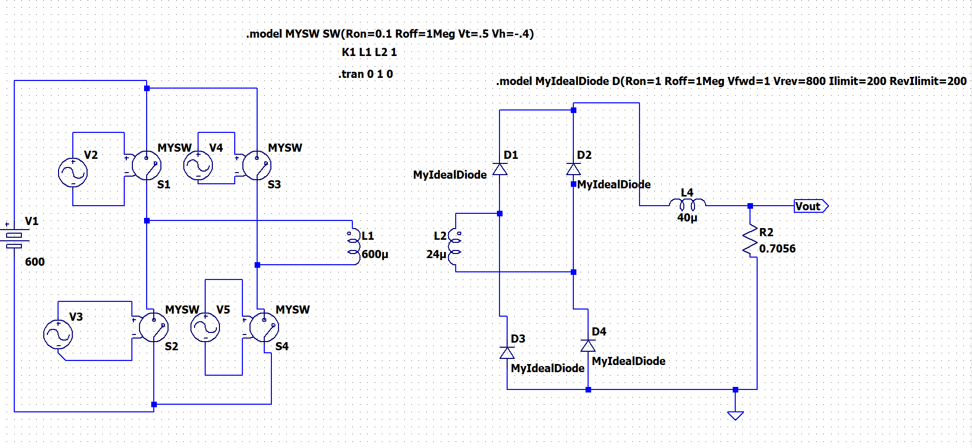
I am trying to simulate a Phasephase shifted full bridge converter in LTspice. I had already simulated it in matlab simulinkMATLAB Simulink and obtained the desired results, but I am redoing it in LTspice to include the effects of non-ideal components. 

In order to avoid the pulse generation, I imported the switching pulses datapoints from simulinkSimulink. I have thoroughly checked it and there's no issue with my switching pulses. However, the same circuit in LTspice behaves very weirdly.

This is my model:

enter image description here

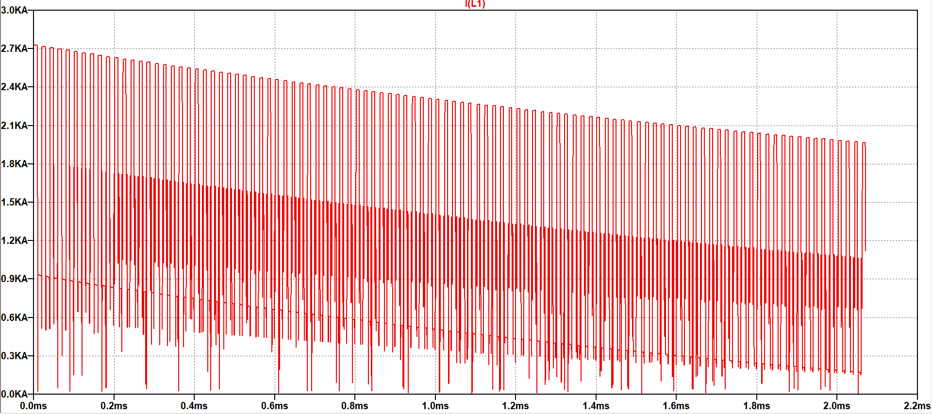
First of all the current on primary is weirdly high, around 3kA where as it is 25A peak in simulinkSimulink. The current wave on primary side is as shown below.
:

enter image description here

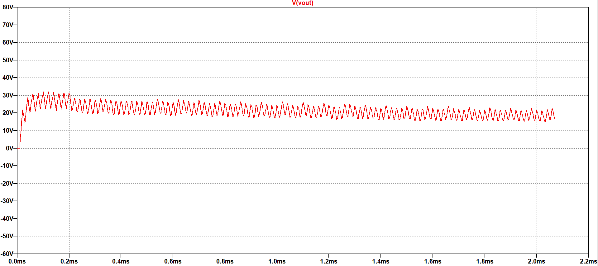
This is the output DC waveform ( whereas II am expecting a stable DC of around 85V as I had obtained in simulinkSimulink.)

enter image description here

I suspect it is an issue with the transformer, but I am not able to pin-point it exactly. Any suggestions are greatly appreciated.

LTspice giving weird results in simulation of Phase Shifted Full Bridge Converter

I am trying to simulate a Phase shifted full bridge converter in LTspice. I had already simulated it in matlab simulink and obtained the desired results, but I am redoing it in LTspice to include the effects of non-ideal components. In order to avoid the pulse generation, I imported the switching pulses datapoints from simulink. I have thoroughly checked it and there's no issue with my switching pulses. However, the same circuit in LTspice behaves very weirdly.

This is my model:

enter image description here

First of all the current on primary is weirdly high, around 3kA where as it is 25A peak in simulink. The current wave on primary side is as shown below.
enter image description here

This is the output DC waveform ( whereas I am expecting stable DC of around 85V as I had obtained in simulink.)

enter image description here

I suspect it is an issue with the transformer, but I am not able to pin-point it exactly. Any suggestions are greatly appreciated.
LTspice giving weird results in simulation of phase shifted full bridge converter

I am trying to simulate a phase shifted full bridge converter in LTspice. I had already simulated it in MATLAB Simulink and obtained the desired results, but I am redoing it in LTspice to include the effects of non-ideal components. 

In order to avoid the pulse generation, I imported the switching pulses datapoints from Simulink. I have thoroughly checked it and there's no issue with my switching pulses. However, the same circuit in LTspice behaves very weirdly.

This is my model:

enter image description here

First of all the current on primary is weirdly high, around 3kA where as it is 25A peak in Simulink. The current wave on primary side is as shown below:

enter image description here

This is the output DC waveform (I am expecting a stable DC of around 85V as I had obtained in Simulink.)

enter image description here

I suspect it is an issue with the transformer, but I am not able to pin-point it exactly. Any suggestions are greatly appreciated.
Source Link

LTspice giving weird results in simulation of Phase Shifted Full Bridge Converter

I am trying to simulate a Phase shifted full bridge converter in LTspice. I had already simulated it in matlab simulink and obtained the desired results, but I am redoing it in LTspice to include the effects of non-ideal components. In order to avoid the pulse generation, I imported the switching pulses datapoints from simulink. I have thoroughly checked it and there's no issue with my switching pulses. However, the same circuit in LTspice behaves very weirdly.

This is my model:

enter image description here

First of all the current on primary is weirdly high, around 3kA where as it is 25A peak in simulink. The current wave on primary side is as shown below.
enter image description here

This is the output DC waveform ( whereas I am expecting stable DC of around 85V as I had obtained in simulink.)

enter image description here

I suspect it is an issue with the transformer, but I am not able to pin-point it exactly. Any suggestions are greatly appreciated.