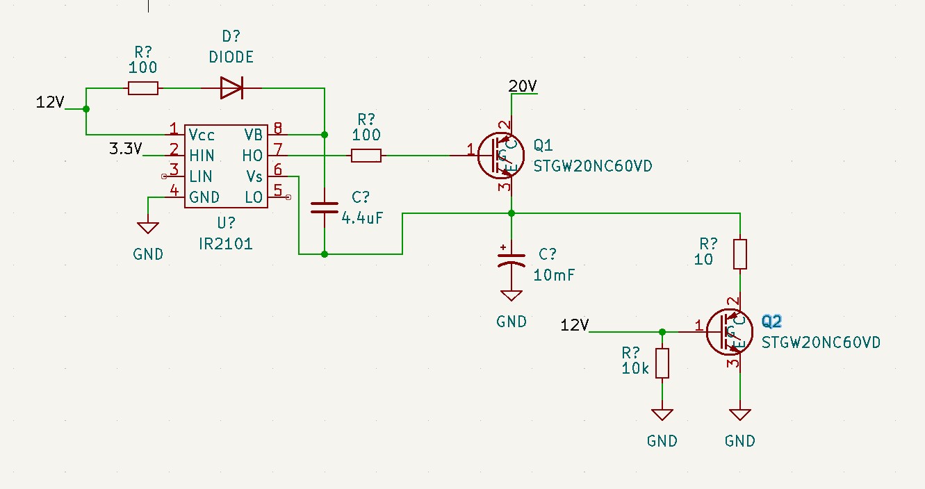
I am trying to implement a high side-side gate driver using IR2101an IR2101. The power supply of the IGBT can go up to 60V60 V and 9A9 A.
The idea is Ito switch ON Q1Q1 using high side-side circuitry and then switch OFF Q1 and switch on Q2 so that the capacitor can discharge through the high power-power 10 ohmΩ resistor.
However theThe problem, however, is that the high side-side gate driver circuitry does not work. If I measure the voltage VB-Vs I get 12V12 V (correct since my 4.4uF cap[tantalum]4 μF tantalum cap charges), if. If I measure VB-HO I get 12V12 V (dontI don't know why this happens), and the voltage at HO-Vs (emitter of Q1) is 0V0 V.
Why is it that if I give a 3.3V3 V signal my output voltage HO is 0V0 V w.r.t. the emitter of Q1.?
Can I please get some help here.? I have seen this gate driver circuitry used in plenty applicationsof applications; I can't, however I cant, get it to work here.

