2
\$\begingroup\$

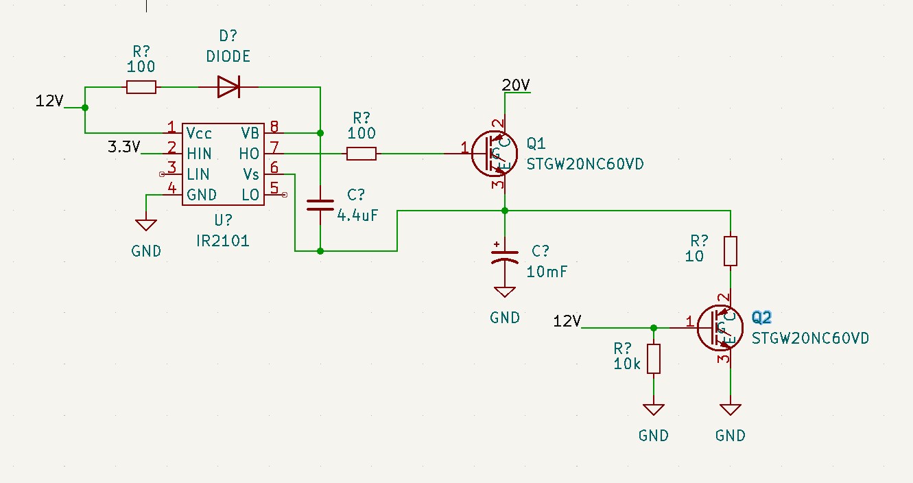
I am trying to implement a high-side gate driver using an IR2101. The power supply of the IGBT can go up to 60 V and 9 A.

The idea is to switch ON Q1 using high-side circuitry and then switch OFF Q1 and switch on Q2 so that the capacitor can discharge through the high-power 10 Ω resistor.

The problem, however, is that the high-side gate driver circuitry does not work. If I measure the voltage VB-Vs I get 12 V (correct since my 4.4 μF tantalum cap charges). If I measure VB-HO I get 12 V (I don't know why this happens), and the voltage at HO-Vs (emitter of Q1) is 0 V.

Why is it that if I give a 3.3 V signal my output voltage HO is 0 V w.r.t. the emitter of Q1?

Can I please get some help here? I have seen this gate driver circuitry used in plenty of applications; I can't, however, get it to work here.

enter image description here

\$\endgroup\$
10
  • 3
    \$\begingroup\$ Such a gate driver requires constant switching to keep the bootstrap capacitor topped up. In the time it takes to make static measurements the UV lockout likely trips. Apply appropriate square waves to both HIN and LIN and use a oscilloscope to view the waveforms. \$\endgroup\$ Commented Aug 23, 2022 at 18:27
  • \$\begingroup\$ My application prevents me to apply square wave for the switching. My application is more of switch the capacitor ON and then OFF, therefore my next switching can therefore be after 5 mins or any random time. \$\endgroup\$
    – Mayur
    Commented Aug 23, 2022 at 18:34
  • 5
    \$\begingroup\$ Then you might have to find a different solution. The high side switch can only be active for a very short time until the bootstrap capacitor voltage gets too low and triggers the UV lockout. These types of drivers are meant for PWM applications that constantly switch... \$\endgroup\$ Commented Aug 23, 2022 at 18:39
  • 1
    \$\begingroup\$ Add a charge pump for the bootstrap capacitor. Or an outright floating/isolated source for it. \$\endgroup\$
    – DKNguyen
    Commented Aug 23, 2022 at 20:39
  • 1
    \$\begingroup\$ Why are you even using an IGBT anyways? It's only 60V at 9A. IGBTs are not the best device in this voltage range. In fact, the IGBTs you are using are rated for 600V. Why? \$\endgroup\$
    – DKNguyen
    Commented Aug 24, 2022 at 5:30

1 Answer 1

2
\$\begingroup\$

The high-side driver in IR2101 can only maintain high output state when the output is switching above some minimum rate that depends on temperature and the size of the bootstrap capacitor.

When the high-side output is static-high, the boost capacitor drains, and the driver switches off to protect the device from linear operation. The driver is designed to drive the controlled device into saturation, i.e. operate it as a switch. It can't do it without the boost capacitor being replenished periodically by switching the high-side output.

Of course, the static-low high-side output can be held indefinitely.

I have seen this gate driver circuitry used in plenty of applications

You'll notice that the high side drive signal is never static-high. It's only high for a short period of time.

To get the circuit to work as-is, add a charge pump to generate the boost voltage externally to the IR2101, so that the high-side driver can maintain operation without switching itself.

\$\endgroup\$
1
  • \$\begingroup\$ Thank you very much. Its the first the first I am hearing about charge pump circuitry. Could you please explain, or help me with a circuitry or direct me somewhere that I can learn about charge pump circuitry and how I can add to it to my current circuitry. \$\endgroup\$
    – Mayur
    Commented Aug 24, 2022 at 15:48

Your Answer

By clicking “Post Your Answer”, you agree to our terms of service and acknowledge you have read our privacy policy.

Not the answer you're looking for? Browse other questions tagged or ask your own question.