Tweeted twitter.com/StackElectronix/status/1569566553691099136
edited body
Source Link

I'm not that familiar with high-speed boards designing. Here I want to route the PCB in a part of which I've used a LAN8720A as the PHY of the ethernet system. According to what I've read about ethernet, the single-ended impedance should be 50 Ω. I've designed my Layer Stack Manager in Altium Designer as below:

enter image description here

To be honest, the results surprised me because the suggested trace width is about 120 mil, which does not seem to be normal. Did I make some mistakes in settings? Or is the 2-layer FR4 material not appropriate?


I saw this question which has the schematic below, using 10 Ω resistors for series termination.

enter image description hereenter image description here

Are these resistors for impedance matching ? Could I use something like that?

I'm not that familiar with high-speed boards designing. Here I want to route the PCB in a part of which I've used a LAN8720A as the PHY of the ethernet system. According to what I've read about ethernet, the single-ended impedance should be 50 Ω. I've designed my Layer Stack Manager in Altium Designer as below:

enter image description here

To be honest, the results surprised me because the suggested trace width is about 120 mil, which does not seem to be normal. Did I make some mistakes in settings? Or is the 2-layer FR4 material not appropriate?


I saw this question which has the schematic below, using 10 Ω resistors for series termination.

enter image description here

Are these resistors for impedance matching ? Could I use something like that?

I'm not that familiar with high-speed boards designing. Here I want to route the PCB in a part of which I've used a LAN8720A as the PHY of the ethernet system. According to what I've read about ethernet, the single-ended impedance should be 50 Ω. I've designed my Layer Stack Manager in Altium Designer as below:

enter image description here

To be honest, the results surprised me because the suggested trace width is about 120 mil, which does not seem to be normal. Did I make some mistakes in settings? Or is the 2-layer FR4 material not appropriate?


I saw this question which has the schematic below, using 10 Ω resistors for series termination.

enter image description here

Are these resistors for impedance matching ? Could I use something like that?
added 8 characters in body; edited title
Source Link
ocrdu
  • 9.3k
  • 23
  • 32
  • 42

Impedance matching in 2 layer-layer FR4 board

I'm not that much familiar with high speed-speed boards designing. hereHere I want to route the PCB which in a part of thatwhich I've used a LAN8720A as the PHY of the ethernet system. asAccording to what I've read about the ethernet, the single ended-ended impedance should be 50 Ω. I've designed my Layer Stack Manager in Altium Designer as below:

enter image description here

To be honest, the results surprised me causebecause the suggested trace width is about 120 mil, which isdoes not seem to be normal. DoDid I make some mistakes in settings? Or is the 2 layer-layer FR4 material is not appropriate?


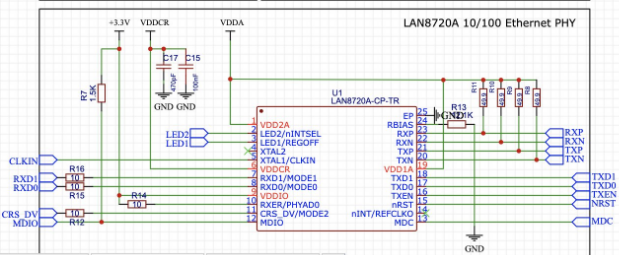
I saw this question which havehas the schematic below, using series termination 10 Ω resistors for series termination.

enter image description here

Are these resistors for impedance matching goal? MayCould I use something like thisthat?

Impedance matching in 2 layer FR4 board

I'm not that much familiar with high speed boards designing. here I want to route the PCB which in a part of that I've used LAN8720A as the PHY of the ethernet system. as I've read about the ethernet, the single ended impedance should be 50 Ω. I've designed my Layer Stack Manager in Altium Designer as below:

enter image description here

To be honest the results surprised me cause the suggested trace width is about 120 mil, which is not seem to be normal. Do I make some mistakes in settings? Or the 2 layer FR4 material is not appropriate?


I saw this question which have the schematic below, using series termination 10 Ω resistors.

enter image description here

Are these resistors for impedance matching goal? May I use something like this?

Impedance matching in 2-layer FR4 board

I'm not that familiar with high-speed boards designing. Here I want to route the PCB in a part of which I've used a LAN8720A as the PHY of the ethernet system. According to what I've read about ethernet, the single-ended impedance should be 50 Ω. I've designed my Layer Stack Manager in Altium Designer as below:

enter image description here

To be honest, the results surprised me because the suggested trace width is about 120 mil, which does not seem to be normal. Did I make some mistakes in settings? Or is the 2-layer FR4 material not appropriate?


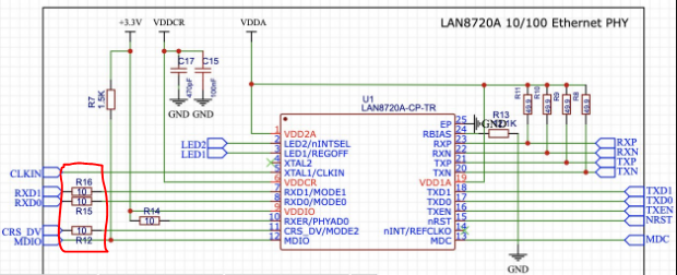
I saw this question which has the schematic below, using 10 Ω resistors for series termination.

enter image description here

Are these resistors for impedance matching ? Could I use something like that?
added 4 characters in body
Source Link
winny
  • 16.8k
  • 6
  • 50
  • 71

I'm not that much familiar with high speed boards designing. here I want to route the PCB which in a part of that I've used LAN8720A as the PHY of the ethernet system. as I've read about the ethernet, the single ended impedance should be 50 Ω. I've designed my Layer Stack Manager in Altium Designer as below:

enter image description here

To be honest the results surprised me cause the suggested trace width is about 120 mil, which is not seem to be normal. Do I make some mistakes in settings? Or the 2 layer FR4 material is not appropriate?


I saw this question which have the schematic below, using series termination 10ohm10 Ω resistors.

enter image description here

areAre these resistors for impedance matching goal? mayMay I use something like this?

I'm not that much familiar with high speed boards designing. here I want to route the PCB which in a part of that I've used LAN8720A as the PHY of the ethernet system. as I've read about the ethernet, the single ended impedance should be 50 Ω. I've designed my Layer Stack Manager in Altium Designer as below:

enter image description here

To be honest the results surprised me cause the suggested trace width is about 120 mil, which is not seem to be normal. Do I make some mistakes in settings? Or the 2 layer FR4 material is not appropriate?


I saw this question which have the schematic below, using series termination 10ohm resistors

enter image description here

are these resistors for impedance matching goal? may I use something like this?

I'm not that much familiar with high speed boards designing. here I want to route the PCB which in a part of that I've used LAN8720A as the PHY of the ethernet system. as I've read about the ethernet, the single ended impedance should be 50 Ω. I've designed my Layer Stack Manager in Altium Designer as below:

enter image description here

To be honest the results surprised me cause the suggested trace width is about 120 mil, which is not seem to be normal. Do I make some mistakes in settings? Or the 2 layer FR4 material is not appropriate?


I saw this question which have the schematic below, using series termination 10 Ω resistors.

enter image description here

Are these resistors for impedance matching goal? May I use something like this?

Became Hot Network Question
appended answer 634536 as supplemental
Source Link
SamGibson
  • 18.3k
  • 5
  • 41
  • 63
Loading
edited tags
Link
Voltage Spike
  • 88.8k
  • 49
  • 90
  • 234
Loading
added 2 characters in body; edited title
Source Link
winny
  • 16.8k
  • 6
  • 50
  • 71
Loading
Source Link
Loading