removed dead link
Source Link

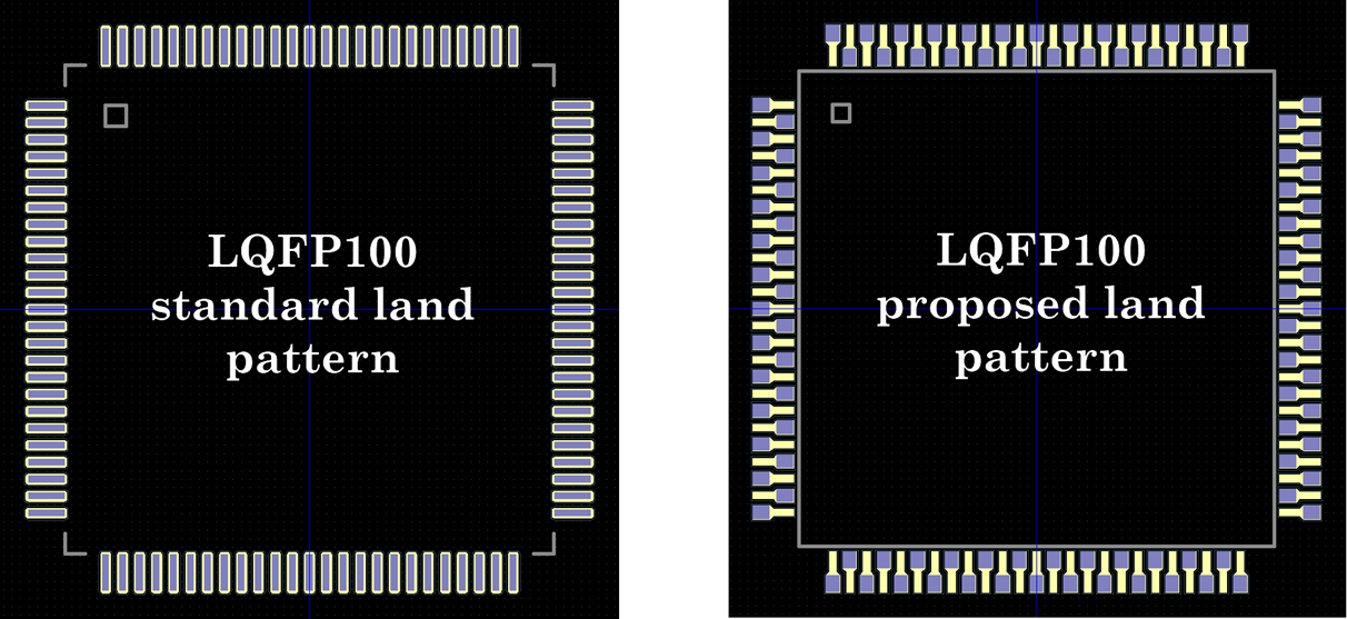
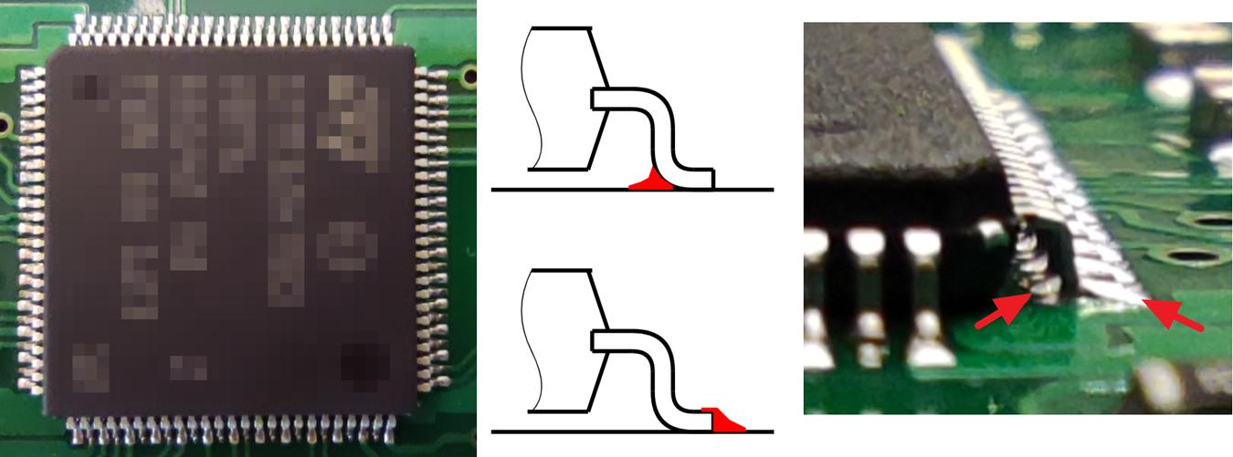
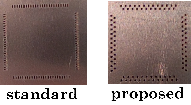
Standard 0.5mm-pitch LQFP stencil paste openings are pretty thin. From my experience, solder paste is often smeared during stencil removal and manual component placement. Here is modified land pattern / stencil configuration for solder bridging prevention (usable only for reflow soldering): LQFP 0.5mm Paste shrink: 0mm Mask swell: 0.05mm Distances between pad centers are the same as standard LQFP48/64/100 (see STM32 datasheet).
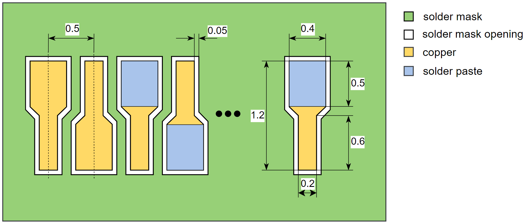
Idea is to use wider stencil openings and place them farther away (alternate paste openings placement): enter image description here
Stencil and land pattern comparison: enter image description here

enter image description here

All drawings/photos in this answer are made by me. Pdf summary: https://www.thundertronics.com/Modified%20LQFP%20land%20pattern%20for%20solder%20bridging%20prevention.pdf

Standard 0.5mm-pitch LQFP stencil paste openings are pretty thin. From my experience, solder paste is often smeared during stencil removal and manual component placement. Here is modified land pattern / stencil configuration for solder bridging prevention (usable only for reflow soldering): LQFP 0.5mm Paste shrink: 0mm Mask swell: 0.05mm Distances between pad centers are the same as standard LQFP48/64/100 (see STM32 datasheet).

Idea is to use wider stencil openings and place them farther away (alternate paste openings placement): enter image description here

Stencil and land pattern comparison: enter image description here

enter image description here

All drawings/photos in this answer are made by me.

deleted 2 characters in body
Source Link

Standard 0.5mm-pitch LQFP stencil paste openings are pretty thin. From my experience, solder paste is often smeared during stencil removal and manual component placement. Here is my modified land pattern / stencil configuration for solder bridging prevention (usable only for reflow soldering): LQFP 0.5mm Paste shrink: 0mm Mask swell: 0.05mm DistanceDistances between pad centers are the same as standard LQFP48/64/100 (see STM32 datasheet).

Idea is to use wider stencil openings and place them farther away (alternate paste openings placement): enter image description here

Stencil and land pattern comparison: enter image description here

enter image description here

All drawings/photos in this answer are made by me. Pdf summary: https://www.thundertronics.com/Modified%20LQFP%20land%20pattern%20for%20solder%20bridging%20prevention.pdf

Standard 0.5mm-pitch LQFP stencil paste openings are pretty thin. From my experience, solder paste is often smeared during stencil removal and manual component placement. Here is my modified land pattern / stencil configuration for solder bridging prevention (usable only for reflow soldering): LQFP 0.5mm Paste shrink: 0mm Mask swell: 0.05mm Distance between pad centers are the same as standard LQFP48/64/100 (see STM32 datasheet).

Idea is to use wider stencil openings and place them farther away (alternate paste openings placement): enter image description here

Stencil and land pattern comparison: enter image description here

enter image description here

All drawings/photos in this answer are made by me. Pdf summary: https://www.thundertronics.com/Modified%20LQFP%20land%20pattern%20for%20solder%20bridging%20prevention.pdf

Standard 0.5mm-pitch LQFP stencil paste openings are pretty thin. From my experience, solder paste is often smeared during stencil removal and manual component placement. Here is modified land pattern / stencil configuration for solder bridging prevention (usable only for reflow soldering): LQFP 0.5mm Paste shrink: 0mm Mask swell: 0.05mm Distances between pad centers are the same as standard LQFP48/64/100 (see STM32 datasheet).

Idea is to use wider stencil openings and place them farther away (alternate paste openings placement): enter image description here

Stencil and land pattern comparison: enter image description here

enter image description here

All drawings/photos in this answer are made by me. Pdf summary: https://www.thundertronics.com/Modified%20LQFP%20land%20pattern%20for%20solder%20bridging%20prevention.pdf

added 4 characters in body
Source Link

Standard 0.5mm-pitch LQFP stencil paste openings are pretty thin. From my experience, solder paste is often smeared during stencil removal and manual component placement. Here is my modified land pattern / stencil configuration for solder bridging prevention (usable only for reflow soldering): LQFP 0.5mm Paste shrink: 0mm Mask swell: 0.05mm Distance between pad centers are the same as standard LQFP48/64/100 (see STM32 datasheet).

Idea is to use wider stencil openings and place them farther away (alternate paste openings placement): enter image description here

Stencil and land pattern comparison: enter image description here

enter image description here

All drawings/photos in this answer are made by me. Pdf summary: https://thundertronics.com/Modified%20LQFP%20land%20pattern%20for%20solder%20bridging%20prevention.pdfhttps://www.thundertronics.com/Modified%20LQFP%20land%20pattern%20for%20solder%20bridging%20prevention.pdf

Standard 0.5mm-pitch LQFP stencil paste openings are pretty thin. From my experience, solder paste is often smeared during stencil removal and manual component placement. Here is my modified land pattern / stencil configuration for solder bridging prevention (usable only for reflow soldering): LQFP 0.5mm Paste shrink: 0mm Mask swell: 0.05mm Distance between pad centers are the same as standard LQFP48/64/100 (see STM32 datasheet).

Idea is to use wider stencil openings and place them farther away (alternate paste openings placement): enter image description here

Stencil and land pattern comparison: enter image description here

enter image description here

All drawings/photos in this answer are made by me. Pdf summary: https://thundertronics.com/Modified%20LQFP%20land%20pattern%20for%20solder%20bridging%20prevention.pdf

Standard 0.5mm-pitch LQFP stencil paste openings are pretty thin. From my experience, solder paste is often smeared during stencil removal and manual component placement. Here is my modified land pattern / stencil configuration for solder bridging prevention (usable only for reflow soldering): LQFP 0.5mm Paste shrink: 0mm Mask swell: 0.05mm Distance between pad centers are the same as standard LQFP48/64/100 (see STM32 datasheet).

Idea is to use wider stencil openings and place them farther away (alternate paste openings placement): enter image description here

Stencil and land pattern comparison: enter image description here

enter image description here

All drawings/photos in this answer are made by me. Pdf summary: https://www.thundertronics.com/Modified%20LQFP%20land%20pattern%20for%20solder%20bridging%20prevention.pdf

added 59 characters in body
Source Link
Loading
added 273 characters in body
Source Link
Loading
Source Link
Loading