Tweeted twitter.com/StackElectronix/status/1585104071870005248
added 20 characters in body
Source Link
ocrdu
  • 9.3k
  • 23
  • 32
  • 42

Output signal distortion from Opampop-amp

I am currently using a TLE2144, and the input signal of 600kHz600 kHz, 4.5Vpp5 Vpp is generated from a function generator. 

Using a voltage follower with TLE2144, I was able to get an output of 4.5Vpp5 Vpp with an input from the function generator, but after it reaches above 510kHz510 kHz, the signal starts distortingto distort on the negative cycle.

The gain bandwidth of TLE2144 is around 5MHz5 MHz, and the slew rate is 27V27 V/usμs. Therefore, I should be getting a good signal on the output, yet the negative cycle of the signal looks slightly distorted. Not sure what the issue is. I do not know what I need to look for.

Schematic:

Dual Supply of +/-12V12 V enter image description here

Image shown below:   (Inputinput: Cyancyan signal, Outputoutput: Yellowyellow signal):

I don't care about the phase difference.

enter image description here

I may have found the issue; even though it mentions that for rhe TLE2144IDW, the gain-bandwidth is 5.9Mhz9 Mhz, they have provided a chart where the signal starts attenuating after 500kHz500 kHz. I will have to look into this more.

enter image description here

Output signal distortion from Opamp

I am currently using TLE2144, and the input signal of 600kHz, 4.5Vpp is generated from a function generator. Using voltage follower with TLE2144, I was able to get an output of 4.5Vpp with an input from function generator but after it reaches above 510kHz, the signal starts distorting on the negative cycle.

The gain bandwidth of TLE2144 is around 5MHz, and the slew rate is 27V/us. Therefore, I should be getting good signal on the output yet the negative cycle of the signal looks slightly distorted. Not sure what the issue is. I do not know what I need to look for.

Schematic:

Dual Supply of +/-12V enter image description here

Image shown below: (Input: Cyan signal, Output: Yellow signal)

I don't care about the phase difference.

enter image description here

I may have found the issue; even though it mentions that for TLE2144IDW, the gain-bandwidth is 5.9Mhz, they have provided a chart where the signal starts attenuating after 500kHz. I will have to look into this more.
enter image description here

Output signal distortion from op-amp

I am currently using a TLE2144, and the input signal of 600 kHz, 4.5 Vpp is generated from a function generator. 

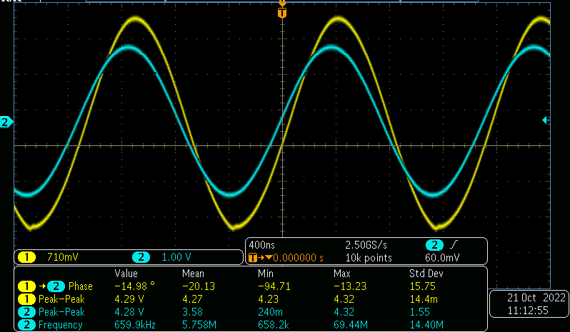
Using a voltage follower with TLE2144, I was able to get an output of 4.5 Vpp with an input from the function generator, but after it reaches above 510 kHz, the signal starts to distort on the negative cycle.

The gain bandwidth of TLE2144 is around 5 MHz, and the slew rate is 27 V/μs. Therefore, I should be getting a good signal on the output, yet the negative cycle of the signal looks slightly distorted. Not sure what the issue is. I do not know what I need to look for.

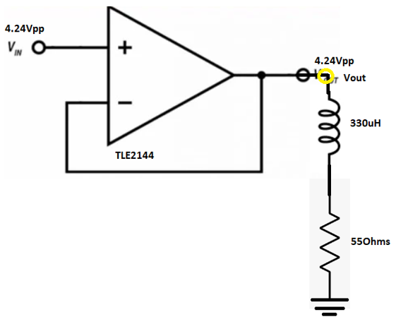
Schematic:

Dual Supply of +/-12 V enter image description here

Image shown below  (input: cyan signal, output: yellow signal):

I don't care about the phase difference.

enter image description here

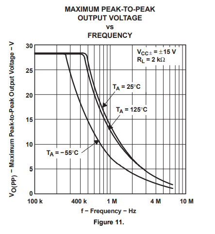
I may have found the issue; even though it mentions that for rhe TLE2144IDW, the gain-bandwidth is 5.9 Mhz, they have provided a chart where the signal starts attenuating after 500 kHz. I will have to look into this more.
enter image description here

possibly found the reason why I have this issue.
Source Link

I am currently using TLE2144, and the input signal of 600kHz, 4.5Vpp is generated from a function generator. Using voltage follower with TLE2144, I was able to get an output of 4.5Vpp with an input from function generator but after it reaches above 510kHz, the signal starts distorting on the negative cycle.

The gain bandwidth of TLE2144 is around 5MHz, and the slew rate is 27V/us. Therefore, I should be getting good signal on the output yet the negative cycle of the signal looks slightly distorted. Not sure what the issue is. I do not know what I need to look for.

Schematic:

Dual Supply of +/-12V enter image description here

Image shown below: (Input: Cyan signal, Output: Yellow signal)

I don't care about the phase difference.

enter image description here

I may have found the issue; even though it mentions that for TLE2144IDW, the gain-bandwidth is 5.9Mhz, they have provided a chart where the signal starts attenuating after 500kHz. I will have to look into this more.

enter image description here

I am currently using TLE2144, and the input signal of 600kHz, 4.5Vpp is generated from a function generator. Using voltage follower with TLE2144, I was able to get an output of 4.5Vpp with an input from function generator but after it reaches above 510kHz, the signal starts distorting on the negative cycle.

The gain bandwidth of TLE2144 is around 5MHz, and the slew rate is 27V/us. Therefore, I should be getting good signal on the output yet the negative cycle of the signal looks slightly distorted. Not sure what the issue is. I do not know what I need to look for.

Schematic:

Dual Supply of +/-12V enter image description here

Image shown below: (Input: Cyan signal, Output: Yellow signal)

I don't care about the phase difference.

enter image description here

I may have found the issue; even though it mentions that for TLE2144IDW, the gain-bandwidth is 5.9Mhz, they have provided a chart where the signal starts attenuating after 500kHz. I will have to look into this more.

enter image description here

Updated schematic
Source Link

I am currently using TLE2144, and the input signal of 600kHz, 4.5Vpp is generated from a function generator. Using voltage follower with TLE2144, I was able to get an output of 4.5Vpp with an input from function generator but after it reaches above 510kHz, the signal starts distorting on the negative cycle.

The gain bandwidth of TLE2144 is around 5MHz, and the slew rate is 27V/us. Therefore, I should be getting good signal on the output yet the negative cycle of the signal looks slightly distorted. Not sure what the issue is. I do not know what I need to look for.

Schematic:

enter image description here Dual Supply of +/-12V enter image description here

Image shown below: (Input: Cyan signal, Output: Yellow signal)

I don't care about the phase difference.

enter image description here

I am currently using TLE2144, and the input signal of 600kHz, 4.5Vpp is generated from a function generator. Using voltage follower with TLE2144, I was able to get an output of 4.5Vpp with an input from function generator but after it reaches above 510kHz, the signal starts distorting on the negative cycle.

The gain bandwidth of TLE2144 is around 5MHz, and the slew rate is 27V/us. Therefore, I should be getting good signal on the output yet the negative cycle of the signal looks slightly distorted. Not sure what the issue is. I do not know what I need to look for.

Schematic:

enter image description here

Image shown below: (Input: Cyan signal, Output: Yellow signal)

I don't care about the phase difference.

enter image description here

I am currently using TLE2144, and the input signal of 600kHz, 4.5Vpp is generated from a function generator. Using voltage follower with TLE2144, I was able to get an output of 4.5Vpp with an input from function generator but after it reaches above 510kHz, the signal starts distorting on the negative cycle.

The gain bandwidth of TLE2144 is around 5MHz, and the slew rate is 27V/us. Therefore, I should be getting good signal on the output yet the negative cycle of the signal looks slightly distorted. Not sure what the issue is. I do not know what I need to look for.

Schematic:

Dual Supply of +/-12V enter image description here

Image shown below: (Input: Cyan signal, Output: Yellow signal)

I don't care about the phase difference.

enter image description here

Added schematic
Source Link
Loading
Source Link
Loading