Vin1 = -Vin2 = var (differential mode). If we vary both input voltages in an opposite direction with the same rate, the local voltages inside the resistor will gradually decrease from the higher to the lower voltage. Because the two voltages are of opposite polarity, a point of zero voltage will appear inside the middle of the resistor; this is the famous "virtual ground". So the input is virtually grounded with its middle point. Twice as much voltage is applied to the resistor, the current is twice as much, and the resistance "seen" by each of the input sources is half the total resistance of the resistor.
I have set an offset (input common-mode) voltage of 5 V and AC (differential) voltage of 100 mV. The phase of Vin2 is 180° (inverted). The output common mode voltage is 9 V.
An experiment with a real ground
If, after the written above, you are not convinced of the need for a "movable ground", I suggest you check it experimentally by connecting the common emitter point E to the real ground.
ConclusionDifferential mode
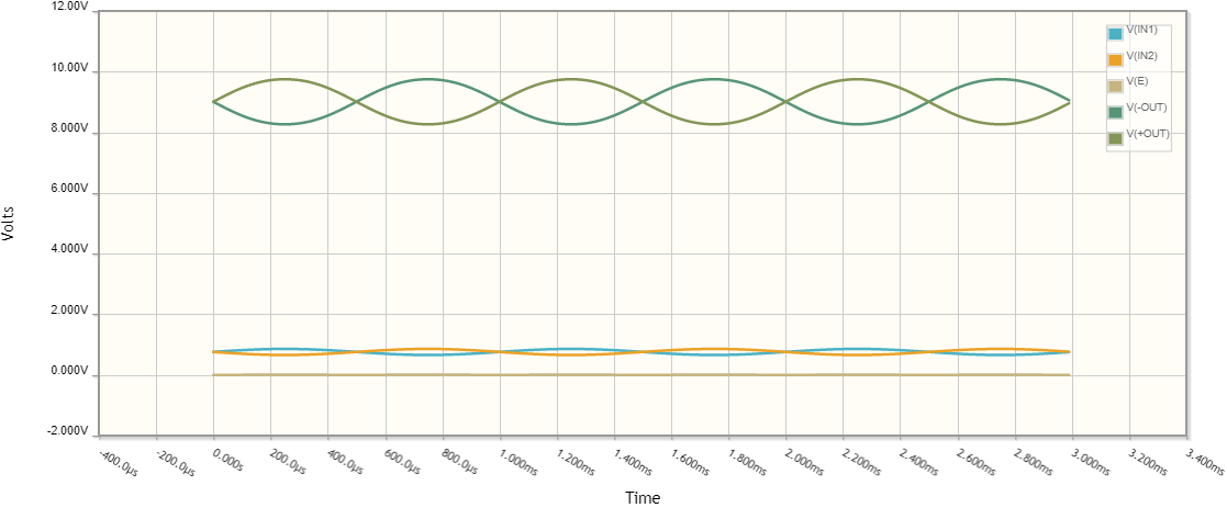
First explore the original (ungrounded) differential pair by setting the voltage of the common emitter point E equal to zero. To do this, set the offset of both input voltage sources to about 0.8 V (I have adusted it to 0.758 V).

Then connect the point E to the real ground.

simulate this circuit

As you can see there is no difference between the two graphs. The two transistors work as common emitter stages with really grounded emitters. The conclusion is that the pure differential mode allows grounding of the emitter point E.
Differential + common mode
Now set 5 V offset (common mode) voltage to both input voltage sources. The result is obvious - because of the excessive base-emitter voltages both transistors are saturated. The conclusion is that the common mode does not allow grounding of the emitter point E; it needs a "flexible" ground.

Conclusion