Became Hot Network Question
edited body
Source Link
winny
  • 16.8k
  • 6
  • 50
  • 71

I have a question regarding this circuit as a basic (!) discrete MOSFET driver switching circuit:

enter image description here

Points I do understand:

  1. Because the MOSFET is most likely a non-LL-MOSFET, we need higher voltages on the GATE-pin in order to charge the internal capacity of the MOSFET to minimize R_(dsDS,on).
  2. Therefore a NPN transistor would be ideal (with R4 and R5), to switch the voltage on the gate pin with the input voltage of the circuit and GND.
  3. R6 is used to limit the possibility of a floating Gate-pingate pin.

Question:

But why do you want to use the PNP-transistor transistor Q2? Which purpose does it have in this exact circuit? Wouldn't it be sufficient to only charge and discharge the Gategate pin via the NPN-transistor transistor connected to the MCU?

Thankful for an explanation on this circuit regarding the PNP-transistor.

I have a question regarding this circuit as a basic (!) discrete MOSFET driver switching circuit:

enter image description here

Points I do understand:

  1. Because the MOSFET is most likely a non-LL-MOSFET, we need higher voltages on the GATE-pin in order to charge the internal capacity of the MOSFET to minimize R_(ds,on).
  2. Therefore a NPN transistor would be ideal (with R4 and R5), to switch the voltage on the gate pin with the input voltage of the circuit and GND.
  3. R6 is used to limit the possibility of a floating Gate-pin.

Question:

But why do you want to use the PNP-transistor Q2? Which purpose does it have in this exact circuit? Wouldn't it be sufficient to only charge and discharge the Gate pin via the NPN-transistor connected to the MCU?

Thankful for an explanation on this circuit regarding the PNP-transistor.
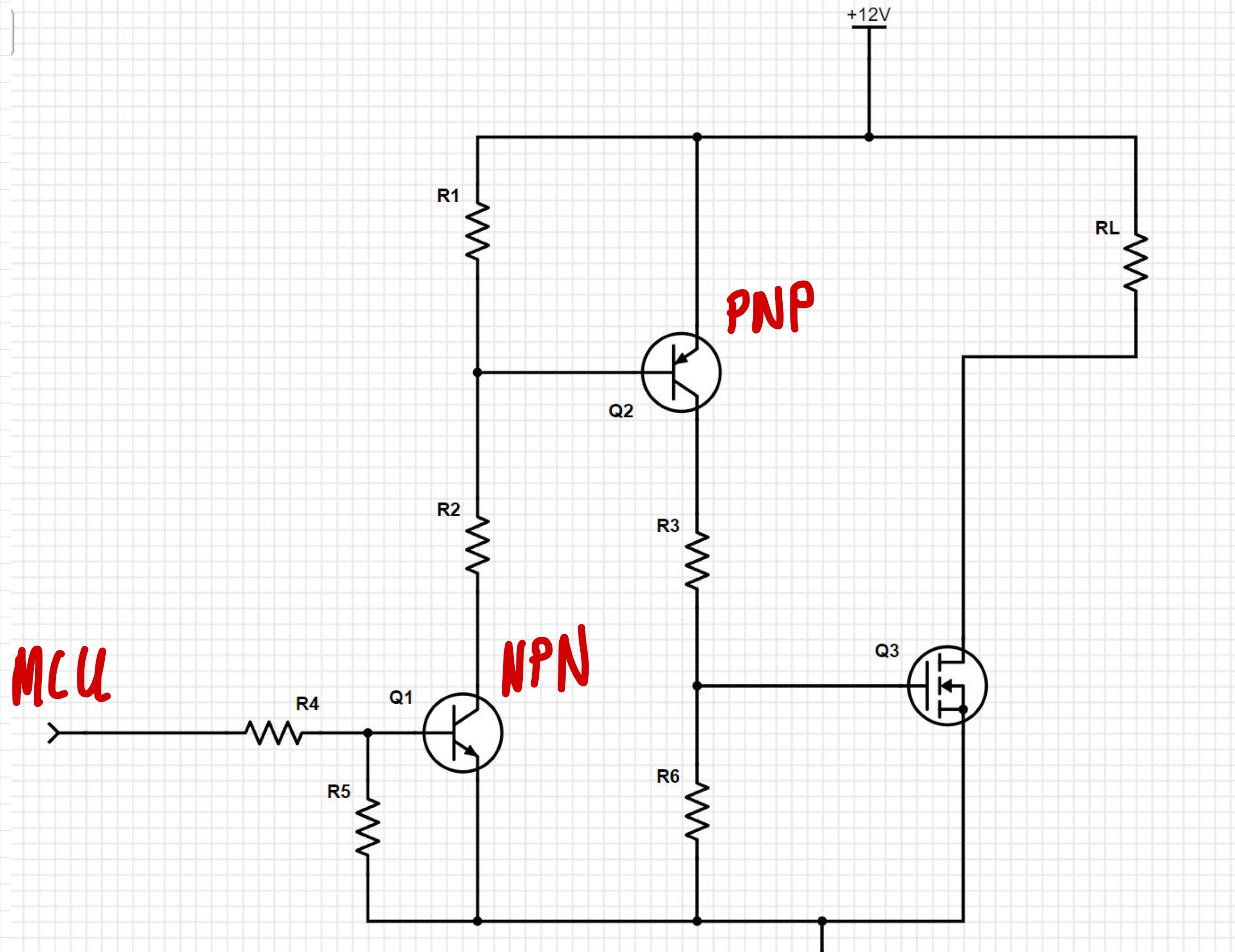
I have a question regarding this circuit as a basic (!) discrete MOSFET driver switching circuit:

enter image description here

Points I do understand:

  1. Because the MOSFET is most likely a non-LL-MOSFET, we need higher voltages on the GATE-pin in order to charge the internal capacity of the MOSFET to minimize R_(DS,on).
  2. Therefore a NPN transistor would be ideal (with R4 and R5), to switch the voltage on the gate pin with the input voltage of the circuit and GND.
  3. R6 is used to limit the possibility of a floating gate pin.

Question:

But why do you want to use the PNP transistor Q2? Which purpose does it have in this exact circuit? Wouldn't it be sufficient to only charge and discharge the gate pin via the NPN transistor connected to the MCU?

Thankful for an explanation on this circuit regarding the PNP-transistor.

Source Link
Dakalaom
  • 561
  • 1
  • 7
  • 15

Discrete N-channel-MOSFET driver switching circuit with NPN and PNP transistor

I have a question regarding this circuit as a basic (!) discrete MOSFET driver switching circuit:

enter image description here

Points I do understand:

  1. Because the MOSFET is most likely a non-LL-MOSFET, we need higher voltages on the GATE-pin in order to charge the internal capacity of the MOSFET to minimize R_(ds,on).
  2. Therefore a NPN transistor would be ideal (with R4 and R5), to switch the voltage on the gate pin with the input voltage of the circuit and GND.
  3. R6 is used to limit the possibility of a floating Gate-pin.

Question:

But why do you want to use the PNP-transistor Q2? Which purpose does it have in this exact circuit? Wouldn't it be sufficient to only charge and discharge the Gate pin via the NPN-transistor connected to the MCU?

Thankful for an explanation on this circuit regarding the PNP-transistor.