Corrected the power supply link
Source Link
Mito
  • 411
  • 2
  • 11

What's the most practical way to merge multiple AC Devices into one single cable?

I thought aboit it, and what if I solder multiple screw terminals on a PCB, fix them tight, attach a 50A AC fuse for safety, and solder and wire everything together with proper thickness cables? I think 6 AWG should be enough for the load that I plan to apply to it, around 50 amperes in total.

Will that work? Will the PCB burn at 50 amperes of load? There will be both AC and DC parts on that PCB.

More details on hardware:

Project requirements:

  • One DC power supply for all DC components
  • One AC aquarium water bubbler
  • A Raspberry Pi 4
  • Some buck converters
  • Steppers (biggest current eaters)
  • Sensors

AC Parts:

Schematic (I'm new to Kicad and electronics in general so it may have some issues):

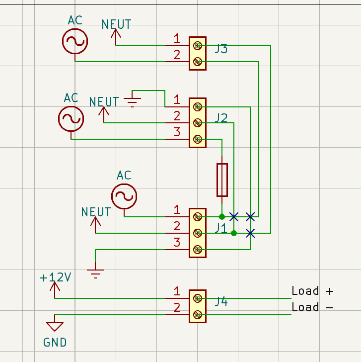
IMPORTANT NOTE: ONLY the bottom 3-screw terminal is connected to the mains. The rest of connectors represent: "hot" of the water air pump/ DC power supply, "neutral" of the water air pump/ DC power supply, and grounding in the case of the PS

Schematicenter image description here

Note:

  • The AC sign was the only symbol I could find for "hot"
  • The "X" symbol means NOT connected. I'm used to the spiral size on schematics so I wanted to point that out

What's the most practical way to merge multiple AC Devices into one single cable?

I thought aboit it, and what if I solder multiple screw terminals on a PCB, fix them tight, attach a 50A AC fuse for safety, and solder and wire everything together with proper thickness cables? I think 6 AWG should be enough for the load that I plan to apply to it, around 50 amperes in total.

Will that work? Will the PCB burn at 50 amperes of load? There will be both AC and DC parts on that PCB.

More details on hardware:

Project requirements:

  • One DC power supply for all DC components
  • One AC aquarium water bubbler
  • A Raspberry Pi 4
  • Some buck converters
  • Steppers (biggest current eaters)
  • Sensors

AC Parts:

Schematic (I'm new to Kicad and electronics in general so it may have some issues):

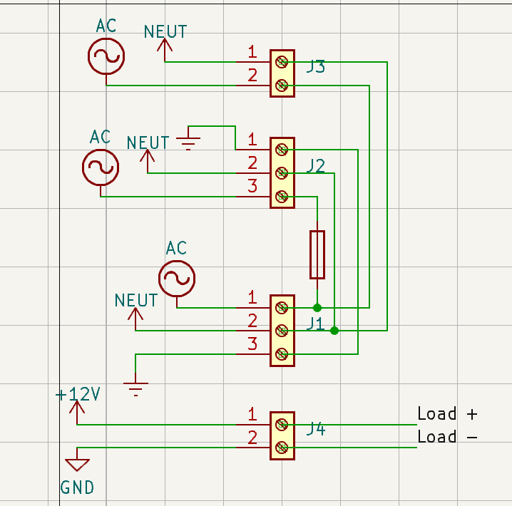
IMPORTANT NOTE: ONLY the bottom 3-screw terminal is connected to the mains. The rest of connectors represent: "hot" of the water air pump/ DC power supply, "neutral" of the water air pump/ DC power supply, and grounding in the case of the PS

Schematic

Note:

  • The AC sign was the only symbol I could find for "hot"
  • The "X" symbol means NOT connected. I'm used to the spiral size on schematics so I wanted to point that out
What's the most practical way to merge multiple AC Devices into one single cable?

I thought aboit it, and what if I solder multiple screw terminals on a PCB, fix them tight, attach a 50A AC fuse for safety, and solder and wire everything together with proper thickness cables? I think 6 AWG should be enough for the load that I plan to apply to it, around 50 amperes in total.

Will that work? Will the PCB burn at 50 amperes of load? There will be both AC and DC parts on that PCB.

More details on hardware:

Project requirements:

  • One DC power supply for all DC components
  • One AC aquarium water bubbler
  • A Raspberry Pi 4
  • Some buck converters
  • Steppers (biggest current eaters)
  • Sensors

AC Parts:

Schematic (I'm new to Kicad and electronics in general so it may have some issues):

IMPORTANT NOTE: ONLY the bottom 3-screw terminal is connected to the mains. The rest of connectors represent: "hot" of the water air pump/ DC power supply, "neutral" of the water air pump/ DC power supply, and grounding in the case of the PS

enter image description here

Note:

  • The AC sign was the only symbol I could find for "hot"
added 15 characters in body; edited title
Source Link
JRE
  • 73.6k
  • 10
  • 112
  • 195

Can I use solder terminals on a PCB to power multiple AC Devicesdevices?

What's the most practical way to merge multiple AC Devices into one single cable?the most practical way to merge multiple AC Devices into one single cable?

I thought ofaboit it, and what if I solder multiple screw terminals on a PCBwhat if I solder multiple screw terminals on a PCB, fix them tighttight, attach a 50A AC fuse50A AC fuse for safety, and solder +and wire everything together with proper thickness cables? (II think 6 AWG6 AWG should be enough for the load that I plan to apply to it, around 50 Ampsamperes in total).

Will that work? Will the PCB burn at 50 ampsamperes of load? (ThereThere will be both ACboth AC and DCDC parts on that PCB).

More details on hardware: Project Requirements

Project requirements: 1 DC Power supply (for all DC components) 1 AC Aquarium Water Bubbler A Raspberry Pi 4, some Buck Converters, Steppers (Biggest Current Eaters), and sensors AC

  • One DC power supply for all DC components
  • One AC aquarium water bubbler
  • A Raspberry Pi 4
  • Some buck converters
  • Steppers (biggest current eaters)
  • Sensors

AC Parts: 12V Power Supply ( Its load will consume most of the electricity) 220 AC Aquarium Air Pump (at max 5w of power consumption, more likely 3) Schematic

Schematic (I'm new to Kicad and electronics in general so it may have some issues):

IMPORTANT NOTE: ONLY the bottom 3-Screwscrew terminal is connected to the mains!. The rest of connectors represent: "hot" of the water air pump/ DC power supply, "neutral" of the water air pump/ DC power supply, and grounding in the case of the PS   

Schematic Note

Note:

  • The AC sign was the only symbol I could find for "Hot""hot"
  • The "X" symbol means NOT connected. I'm used to the spiral size on schematics so I wanted to point that out

Can I use solder terminals on a PCB to power multiple AC Devices?

What's the most practical way to merge multiple AC Devices into one single cable? I thought of it, and what if I solder multiple screw terminals on a PCB, fix them tight, attach a 50A AC fuse for safety, and solder + wire everything together with proper thickness cables? (I think 6 AWG should be enough for the load that I plan to apply to it, around 50 Amps in total) Will that work? Will the PCB burn at 50 amps of load? (There will be both AC and DC parts on that PCB)

More details on hardware: Project Requirements: 1 DC Power supply (for all DC components) 1 AC Aquarium Water Bubbler A Raspberry Pi 4, some Buck Converters, Steppers (Biggest Current Eaters), and sensors AC Parts: 12V Power Supply ( Its load will consume most of the electricity) 220 AC Aquarium Air Pump (at max 5w of power consumption, more likely 3) Schematic (I'm new to Kicad and electronics in general so it may have some issues):

IMPORTANT NOTE: ONLY the bottom 3-Screw terminal is connected to the mains! The rest of connectors represent: "hot" of the water air pump/ DC power supply, "neutral" of the water air pump/ DC power supply, and grounding in the case of the PS  Schematic Note:

  • The AC sign was the only symbol I could find for "Hot"
  • The "X" symbol means NOT connected. I'm used to the spiral size on schematics so I wanted to point that out

Can I use solder terminals on a PCB to power multiple AC devices?

What's the most practical way to merge multiple AC Devices into one single cable?

I thought aboit it, and what if I solder multiple screw terminals on a PCB, fix them tight, attach a 50A AC fuse for safety, and solder and wire everything together with proper thickness cables? I think 6 AWG should be enough for the load that I plan to apply to it, around 50 amperes in total.

Will that work? Will the PCB burn at 50 amperes of load? There will be both AC and DC parts on that PCB.

More details on hardware:

Project requirements:

  • One DC power supply for all DC components
  • One AC aquarium water bubbler
  • A Raspberry Pi 4
  • Some buck converters
  • Steppers (biggest current eaters)
  • Sensors

AC Parts:

Schematic (I'm new to Kicad and electronics in general so it may have some issues):

IMPORTANT NOTE: ONLY the bottom 3-screw terminal is connected to the mains. The rest of connectors represent: "hot" of the water air pump/ DC power supply, "neutral" of the water air pump/ DC power supply, and grounding in the case of the PS 

Schematic

Note:

  • The AC sign was the only symbol I could find for "hot"
  • The "X" symbol means NOT connected. I'm used to the spiral size on schematics so I wanted to point that out
Source Link
Mito
  • 411
  • 2
  • 11

Can I use solder terminals on a PCB to power multiple AC Devices?

What's the most practical way to merge multiple AC Devices into one single cable? I thought of it, and what if I solder multiple screw terminals on a PCB, fix them tight, attach a 50A AC fuse for safety, and solder + wire everything together with proper thickness cables? (I think 6 AWG should be enough for the load that I plan to apply to it, around 50 Amps in total) Will that work? Will the PCB burn at 50 amps of load? (There will be both AC and DC parts on that PCB)

More details on hardware: Project Requirements: 1 DC Power supply (for all DC components) 1 AC Aquarium Water Bubbler A Raspberry Pi 4, some Buck Converters, Steppers (Biggest Current Eaters), and sensors AC Parts: 12V Power Supply ( Its load will consume most of the electricity) 220 AC Aquarium Air Pump (at max 5w of power consumption, more likely 3) Schematic (I'm new to Kicad and electronics in general so it may have some issues):

IMPORTANT NOTE: ONLY the bottom 3-Screw terminal is connected to the mains! The rest of connectors represent: "hot" of the water air pump/ DC power supply, "neutral" of the water air pump/ DC power supply, and grounding in the case of the PS Schematic Note:

  • The AC sign was the only symbol I could find for "Hot"
  • The "X" symbol means NOT connected. I'm used to the spiral size on schematics so I wanted to point that out