0
\$\begingroup\$

What's the most practical way to merge multiple AC Devices into one single cable?

I thought aboit it, and what if I solder multiple screw terminals on a PCB, fix them tight, attach a 50A AC fuse for safety, and solder and wire everything together with proper thickness cables? I think 6 AWG should be enough for the load that I plan to apply to it, around 50 amperes in total.

Will that work? Will the PCB burn at 50 amperes of load? There will be both AC and DC parts on that PCB.

More details on hardware:

Project requirements:

  • One DC power supply for all DC components
  • One AC aquarium water bubbler
  • A Raspberry Pi 4
  • Some buck converters
  • Steppers (biggest current eaters)
  • Sensors

AC Parts:

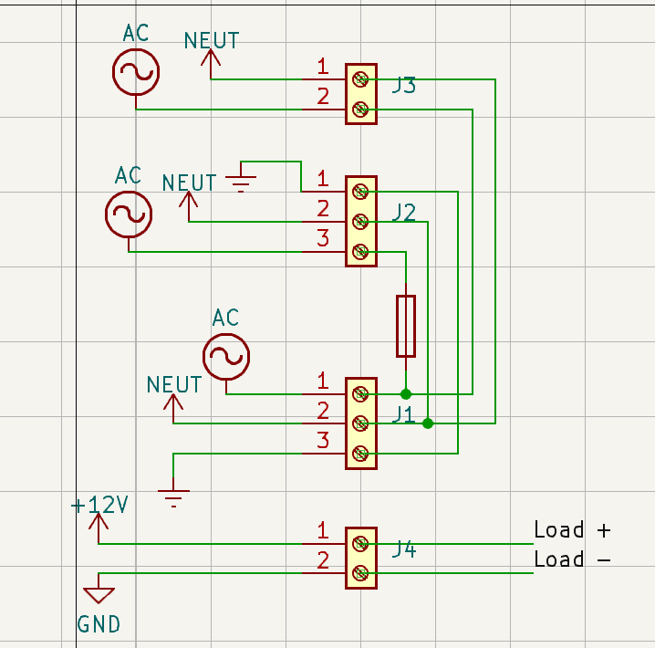
Schematic (I'm new to Kicad and electronics in general so it may have some issues):

IMPORTANT NOTE: ONLY the bottom 3-screw terminal is connected to the mains. The rest of connectors represent: "hot" of the water air pump/ DC power supply, "neutral" of the water air pump/ DC power supply, and grounding in the case of the PS

enter image description here

Note:

  • The AC sign was the only symbol I could find for "hot"
\$\endgroup\$
9
  • \$\begingroup\$ "the spiral size on schematics"? \$\endgroup\$
    – Hearth
    Commented Mar 5, 2023 at 19:49
  • \$\begingroup\$ @Hearth By that I mean this: electronics-notes.com/articles/analogue_circuits/… , more like a crossing over \$\endgroup\$
    – Mito
    Commented Mar 5, 2023 at 20:15
  • \$\begingroup\$ The 12 volt power supply you link to will only draw about 3 Amp at 120 V - no need for giant wires or terminals. Wires crossing without a dot already imply "no connection". Your added X's only add confusion. \$\endgroup\$ Commented Mar 5, 2023 at 20:34
  • \$\begingroup\$ @PeterBennett My mistake, I added the 30A version, not the 50A, I corrected it. Note I'm in Romania, Europe so we're at 220V. The power supply itself won't draw much current, but the motors, RPI and sensors will. In reality it shouldn't go beyond 25 amps, but with the spikes that can occur it's better to be safe \$\endgroup\$
    – Mito
    Commented Mar 5, 2023 at 20:42
  • \$\begingroup\$ I was pointing out that the AC current will be quite low, so there is no need for large wire and connectors for it. If the current on the 12 volt circuits will be 30 - 50 Amp, you do need larger wire for those loads. \$\endgroup\$ Commented Mar 5, 2023 at 20:51

1 Answer 1

0
\$\begingroup\$

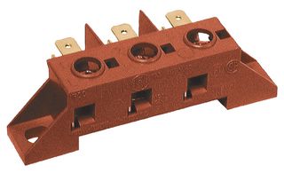
Use a faston tab terminal block.

faston terminal block.

This Hylec model has 3 screw terminals connected to a set of tabs for crimped on terminals. https://www.hylec-apl.com/Emech-Terminals-Accessories/Screw-to-Tab-Terminal-Block/FV110.html

\$\endgroup\$
3
  • \$\begingroup\$ Is it mountable on a PCB? I needed all the components to fit nicely on a custom designed one. Could you provide me a link to it? Also, why do you prefer this one to the screw terminal ones? I do feel like the terminals would not be able to conduct the required 50A, though I'm not sure. Do you know any terminal that can be both soldered and handle that pretty big current? \$\endgroup\$
    – Mito
    Commented Mar 5, 2023 at 20:36
  • \$\begingroup\$ This is a gadget that connects several faston tags to a screw terminal x3 (there are 3 separate buses L N Ground). Crimped terminals are much more reliable that soldering to a board.Don't mount of the PCB if possible. But if you really want to go for a PCB use a "screw terminal strip" instead. \$\endgroup\$
    – D Duck
    Commented Mar 5, 2023 at 20:54
  • \$\begingroup\$ If you follow the correct procedures and guide lines no problem placing the terminals on a PCB. These rules depend on the location and environment. This is a relative common practice in the US on many appliances. \$\endgroup\$
    – Gil
    Commented Mar 5, 2023 at 23:30

Your Answer

By clicking “Post Your Answer”, you agree to our terms of service and acknowledge you have read our privacy policy.

Not the answer you're looking for? Browse other questions tagged or ask your own question.