Address open collector output; added 85 characters in body
Source Link
Simon Fitch
  • 47.4k
  • 3
  • 25
  • 135

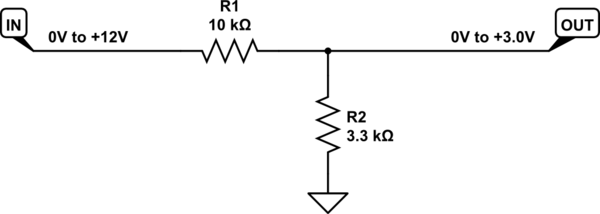
A potential divider is perfectly fine (as long as the sensor ouptut is not open collector, see my last suggestion below):
schematic

simulate this circuit – Schematic created using CircuitLab

The relationship between input and output potentials is:

$$ V_{OUT} = V_{IN} \times \frac{R_2}{R_1+R_2} $$

If there's any chance that the input might stray outside the bounds 0V to 12V, this will also restrict current flowing via the input protection diodes of the GPIO line.

If you wish to power your hall sensors from 5V, you need to increase R2 to compensate. Use the above formula to solve for an appropriate R1, given \$V_{IN}=+5V\$.

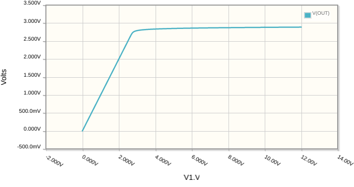
If you can't yet decide whether to power your sensor from a 12V or 5V supply (or anything over 5V for that matter), then you can clamp the signal's potential with a zener diode, to handle almost any maximum input potential:

schematic

simulate this circuit

That gets you this response (Y axis), from an input (X axis) sweeping from 0V to +12V:

enter image description here

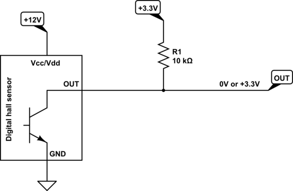
I suspect that your sensor may have an open collector (or open drain) output, in which case, the solution is even simpler:
schematic

simulate this circuit

No protection necessary here, just a single pull-up resistor to +3.3V, but beware that if the sensor output is not open collector, you'll break the GPIO. Check the sensor's datasheet!

A potential divider is perfectly fine:

schematic

simulate this circuit – Schematic created using CircuitLab

The relationship between input and output potentials is:

$$ V_{OUT} = V_{IN} \times \frac{R_2}{R_1+R_2} $$

If there's any chance that the input might stray outside the bounds 0V to 12V, this will also restrict current flowing via the input protection diodes of the GPIO line.

If you wish to power your hall sensors from 5V, you need to increase R2 to compensate. Use the above formula to solve for an appropriate R1, given \$V_{IN}=+5V\$.

If you can't yet decide whether to power your sensor from a 12V or 5V supply (or anything over 5V for that matter), then you can clamp the signal's potential with a zener diode, to handle almost any maximum input potential:

schematic

simulate this circuit

That gets you this response (Y axis), from an input (X axis) sweeping from 0V to +12V:

enter image description here

A potential divider is perfectly fine (as long as the sensor ouptut is not open collector, see my last suggestion below):

schematic

simulate this circuit – Schematic created using CircuitLab

The relationship between input and output potentials is:

$$ V_{OUT} = V_{IN} \times \frac{R_2}{R_1+R_2} $$

If there's any chance that the input might stray outside the bounds 0V to 12V, this will also restrict current flowing via the input protection diodes of the GPIO line.

If you wish to power your hall sensors from 5V, you need to increase R2 to compensate. Use the above formula to solve for an appropriate R1, given \$V_{IN}=+5V\$.

If you can't yet decide whether to power your sensor from a 12V or 5V supply (or anything over 5V for that matter), then you can clamp the signal's potential with a zener diode, to handle almost any maximum input potential:

schematic

simulate this circuit

That gets you this response (Y axis), from an input (X axis) sweeping from 0V to +12V:

enter image description here

I suspect that your sensor may have an open collector (or open drain) output, in which case, the solution is even simpler:

schematic

simulate this circuit

No protection necessary here, just a single pull-up resistor to +3.3V, but beware that if the sensor output is not open collector, you'll break the GPIO. Check the sensor's datasheet!

added 951 characters in body
Source Link
Simon Fitch
  • 47.4k
  • 3
  • 25
  • 135

A potential divider is perfectly fine:

schematic

simulate this circuit – Schematic created using CircuitLab

The relationship between input and output potentials is:

$$ V_{OUT} = V_{IN} \times \frac{R_2}{R_1+R_2} $$

If there's any chance that the input might stray outside the bounds 0V to 12V, this will also restrict current flowing via the input protection diodes of the GPIO line.

If you wish to power your hall sensors from 5V, you need to increase R2 to compensate. Use the above formula to solve for an appropriate R1, given \$V_{IN}=+5V\$.

If you can't yet decide whether to power your sensor from a 12V or 5V supply (or anything over 5V for that matter), then you can clamp the signal's potential with a zener diode, to handle almost any maximum input potential:

schematic

simulate this circuit

That gets you this response (Y axis), from an input (X axis) sweeping from 0V to +12V:

enter image description here

A potential divider is perfectly fine:

schematic

simulate this circuit – Schematic created using CircuitLab

If there's any chance that the input might stray outside the bounds 0V to 12V, this will also restrict current flowing via the input protection diodes of the GPIO line.

A potential divider is perfectly fine:

schematic

simulate this circuit – Schematic created using CircuitLab

The relationship between input and output potentials is:

$$ V_{OUT} = V_{IN} \times \frac{R_2}{R_1+R_2} $$

If there's any chance that the input might stray outside the bounds 0V to 12V, this will also restrict current flowing via the input protection diodes of the GPIO line.

If you wish to power your hall sensors from 5V, you need to increase R2 to compensate. Use the above formula to solve for an appropriate R1, given \$V_{IN}=+5V\$.

If you can't yet decide whether to power your sensor from a 12V or 5V supply (or anything over 5V for that matter), then you can clamp the signal's potential with a zener diode, to handle almost any maximum input potential:

schematic

simulate this circuit

That gets you this response (Y axis), from an input (X axis) sweeping from 0V to +12V:

enter image description here

Source Link
Simon Fitch
  • 47.4k
  • 3
  • 25
  • 135

A potential divider is perfectly fine:

schematic

simulate this circuit – Schematic created using CircuitLab

If there's any chance that the input might stray outside the bounds 0V to 12V, this will also restrict current flowing via the input protection diodes of the GPIO line.